


THEORY OF OPERATION
E-4 E-4
EAGLE™ 10,000
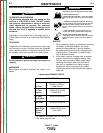
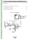
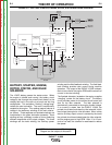
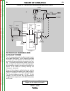
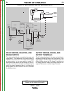
NOTE: Unshaded areas of Block Logic
Diagram are the subject of discussion
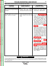
WELD WINDING, REACTOR, AND
RANGE SWITCH
The stator weld winding is connected to the reactor and
range switch. The inductance in the reactor offers an
impedance to current flow. The reactor coil is tapped
at various points. As the range switch is rotated, dif-
ferent amounts of reactor coil are brought into the cur-
rent path. As more turns of reactor are brought into the
circuit, the more impedance there is to current flow.
Simply stated, the more reactor in the circuit, the lower
the welding current.
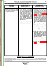
OUTPUT BRIDGE, CHOKE, AND
OUTPUT TERMINALS
The AC voltage developed in the stator weld winding is
delivered, through the reactor and range switch, to the
output bridge. The DC output current path is from the
Output Bridge, where the AC voltage is rectified to a
DC voltage, and then through the choke, where the DC
output is filtered and on to the Output Terminals.
S
TARTER ENGINE
B
ATTERY
IDLER
S
OLENOID
OUTPUT
CONTROL
MECHANICAL
ROTATION
F
IELD
C
APACITOR
R
OTOR
S
LIP
RINGS
1
15 & 230VAC
R
ECEPTACLES
R
OTOR
STATOR
S
TATOR
R
EACTOR
RANGE
SWITCH
OUTPUT
BRIDGE
C
HOKE
A
C
AC
T
ERMINAL
T
ERMINAL
FLYWHEEL
ALTERNATOR
PRINTED CIRCUIT
BOARD
TOROIDTOROID
P
OSITIVEPOSITIVE
N
EGATIVE
FIGURE E.4 – WELD WINDING, REACTOR, AND RANGE SWITCH
Return to Section TOC Return to Section TOC Return to Section TOC Return to Section TOC
Return to Master TOC Return to Master TOC Return to Master TOC Return to Master TOC