


THEORY OF OPERATION
E-3 E-3
EAGLE™ 10,000
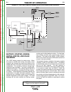
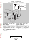
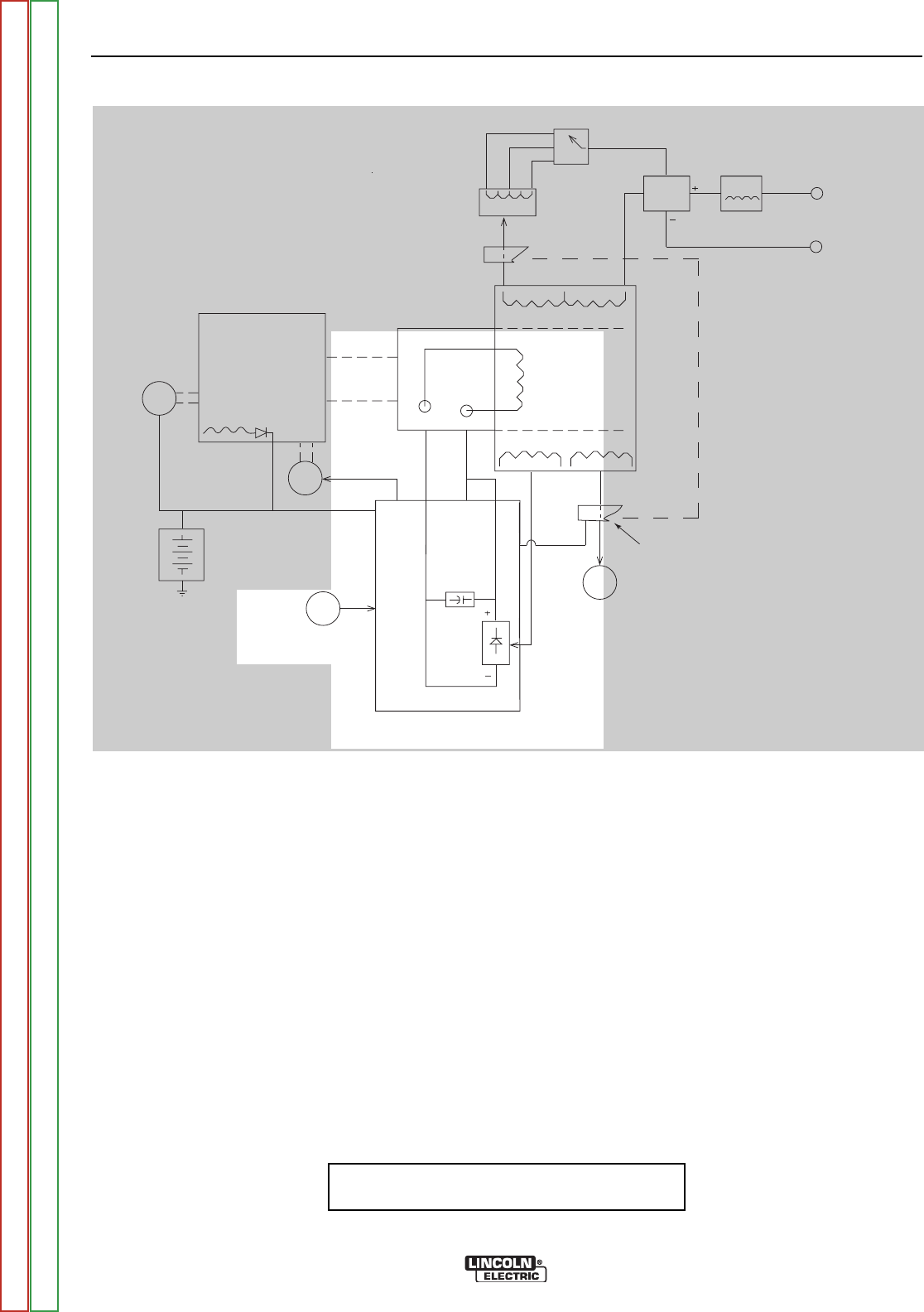
ROTOR FIELD FEEDBACK AND
AUXILIARY POWER
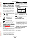
The AC voltage developed in the field winding is fed to
the full wave field bridge. The DC output of the bridge
is filtered by the field capacitor and controlled by the
printed circuit board according to the output control set-
ting. This filtered and controlled voltage is fed to the
rotor winding via the brush and slip ring configuration.
As the feedback voltage is increased or decreased, the
outputs of the weld and auxiliary windings are
increased or decreased.
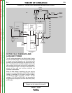
When full field voltage is applied to the rotor and the
engine is running at high speed (3700 RPM), a 230 AC
voltage is developed in the stator auxiliary winding.
This winding is tapped to provide 115 VAC. The two
voltages, (115 VAC and 230 VAC), are connected to
the appropriate receptacles and offer 9000 watts (total)
of AC power.
FIGURE E.3 – ROTOR FIELD FEEDBACK AND AUXILIARY POWER
S
TARTER ENGINE
BATTERY
IDLER
SOLENOID
OUTPUT
CONTROL
MECHANICAL
R
OTATION
FIELD
CAPACITOR
ROTOR
SLIP
R
INGS
115 & 230VAC
R
ECEPTACLES
R
OTOR
STATOR
STATOR
REACTOR
RANGE
S
WITCH
O
UTPUT
B
RIDGE
CHOKE
AC
AC
T
ERMINAL
TERMINAL
FLYWHEEL
ALTERNATOR
PRINTED CIRCUIT
BOARD
TOROIDTOROID
POSITIVEPOSITIVE
NEGATIVE
NOTE: Unshaded areas of Block Logic
Diagram are the subject of discussion
Return to Section TOC Return to Section TOC Return to Section TOC Return to Section TOC
Return to Master TOC Return to Master TOC Return to Master TOC Return to Master TOC