


ENGINE THROTTLE ADJUSTMENT TEST (continued)
11. If either of the readings is incorrect, adjust the
throttle as follows:
Adjust HIGH IDLE: Use the 3/8” wrench to turn
the spring-loaded adjustment nut. See Figure
F.8 for location of the adjustment nut. Turn the
nut clockwise to increase HIGH IDLE speed.
Adjust the speed until the tach reads between
3650 and 3750 RPM.
Adjust LOW IDLE: First make sure there is no
load on the machine. Set the IDLE switch to
AUTO and wait for the engine to change to low
idle speed. Use the 3/8” wrench to adjust the
solenoid nut, which changes the amount of
throw in the throttle lever arm. See Figure F.8
for location of the adjustment nut. Adjust the
nut until the tach reads between 2150 and
2250 RPM.
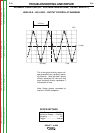
Frequency Counter Method
1. Plug the frequency counter into one of the 115
VAC auxiliary receptacles.
2. Start the engine and check the frequency
counter. At HIGH IDLE (3700 RPM), the
counter should read 60.8 to 62.5 Hz. At LOW
IDLE (2200 RPM), the counter should read
35.8 to 37.5 Hz. Note that these are median
measurements; hertz readings may vary
slightly above or below.
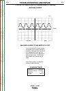
3. If either of the readings is incorrect, adjust the
throttle as follows:
Adjust HIGH IDLE: Use the 3/8” wrench to turn
the spring-loaded adjustment nut. See Figure
F.7 for location of the adjustment nut. Turn the
nut clockwise to increase HIGH IDLE speed.
Adjust the speed until the frequency reads
between 60.8 and 62.5 Hz.
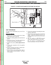
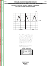
Adjust LOW IDLE: First make sure there is no
load on the machine. Set the IDLER switch to
AUTO and wait for the engine to change to low
idle speed. Use the 3/8” wrench to adjust the
solenoid nut, which changes the amount of
throw in the throttle lever arm. See Figure F.8
for location of the adjustment nut. Adjust the
nut until the frequency reads between 35.8 and
375.Hz.
TROUBLESHOOTING AND REPAIR
F-29 F-29
EAGLE™ 10,000
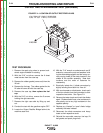
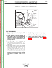
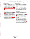
Throttle
linkage
Choke
Cable
3/8" High Idle
Adjustment Nut
Solenoid
H
ousing
3/8" Low Idle
Adjustment
Nut
R
od
M
uffler
FIGURE F.7
HIGH IDLE ADJUSTMENT NUT
FIGURE F.8
LOW IDLE ADJUSTMENT NUT
Return to Section TOC Return to Section TOC Return to Section TOC Return to Section TOC
Return to Master TOC Return to Master TOC Return to Master TOC Return to Master TOC