


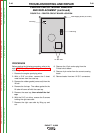
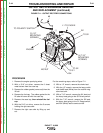
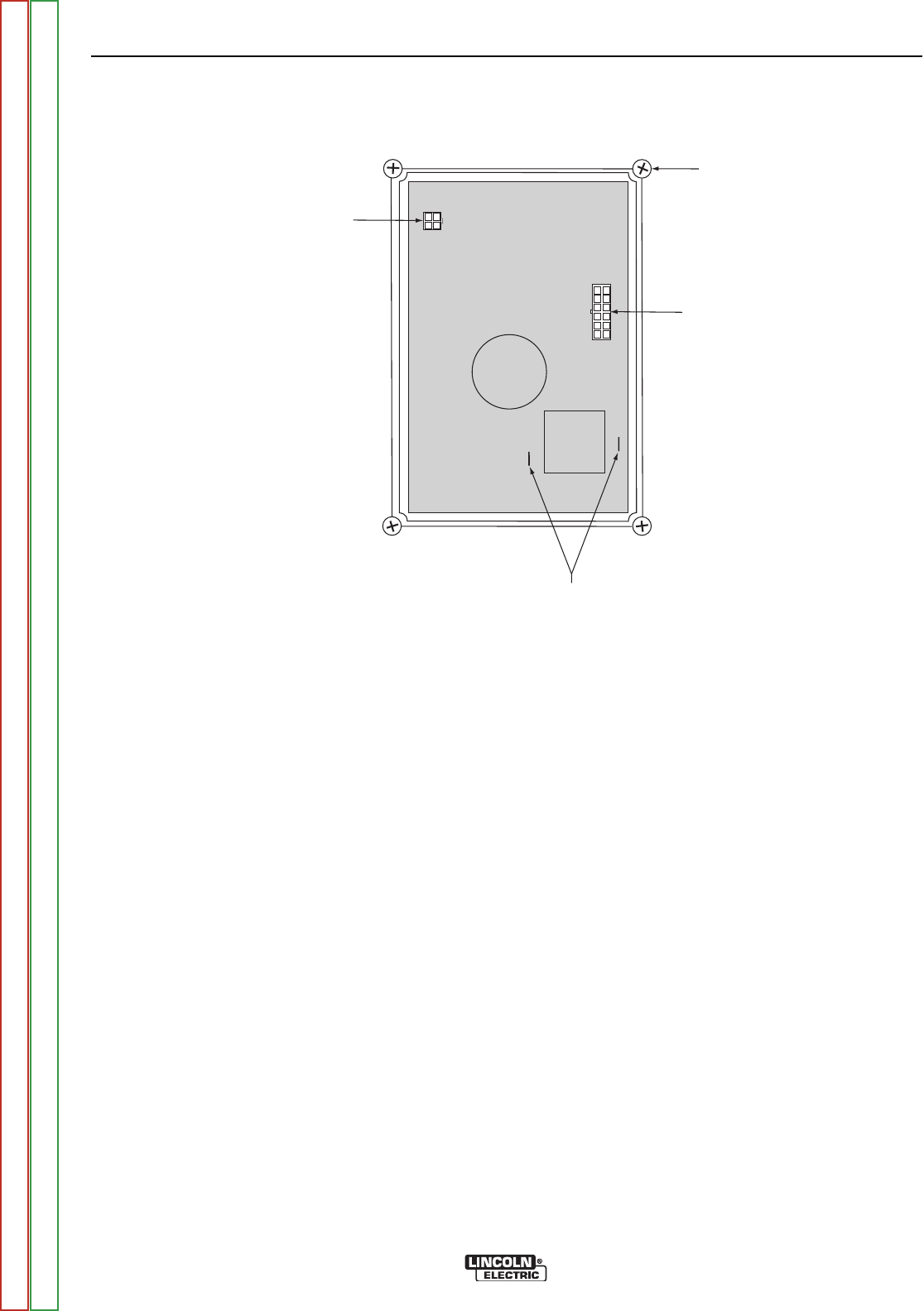
12 Pin Plug
4
Pin Plug
4
Self Tapping Screws (at corners)
1/4" Q.C. Tabs
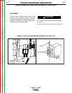
FIGURE F.10 - PRINTED CIRCUIT BOARD LOCATION
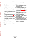
PRINTED CIRCUIT BOARD REMOVAL
AND REPLACEMENT (continued)
PROCEDURE
Before starting the following procedure, refer to the
topic “PC Board Troubleshooting Procedures”
at the beginning of this section.
1. Remove the engine spark plug wires.
2. With a 5/16” nut driver, remove the 6 sheet
metal screws from the case top.
3. Remove the rubber gasket (cover seal) from the
lift bail.
4. Remove the fuel cap. The rubber gasket for the
fill tube will come off with the case top.
5. Remove the case top, then reinstall the fuel
cap.
6. With the 5/16” nut driver, remove the 5 screws
holding the right case side.
7. Remove the right case side by lifting up and
out.
8. Remove the 12-pin molex plug from the
Printed circuit board.
9. Remove 4-pin molex from the current sensing
leads.
10. Remove leads from two 1/4” Q.C. connectors.
TROUBLESHOOTING AND REPAIR
F-40 F-40
EAGLE™ 10,000
Return to Section TOC Return to Section TOC Return to Section TOC Return to Section TOC
Return to Master TOC Return to Master TOC Return to Master TOC Return to Master TOC