


Troubleshooting—GS2 Display 1800
Continued onnext page CF86321,0000335-19-23MAY11-1/2
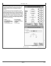
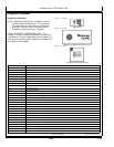
Diagnostic Addresses
Diagnostic Addresses
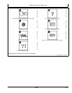
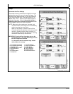
NOTE: Diagnostic addresses are available to access
specic diagnostic information. This information
can assist the John Deere Dealer in diagnosing
problems. Different device controllers can be
selected from drop-down box, as shown.
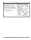
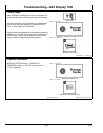
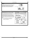
Select DIAGNOSTIC ADDRESSES button. The
number of devices available will depend upon machine
conguration. The list of addresses can be scrolled up or
down with rotary thumb wheel. Selecting an address will
show data for that address.
PC8663 —UN—05AUG05
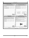
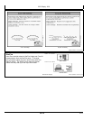
MENU button
PC8655 —UN—05AUG05
MESSAGE CENTER button (With Info Icon)
PC8668 —UN—05AUG05
DIAGNOSTIC ADDRESSES softkey
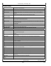
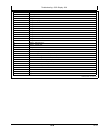
Address Number Address Name
008
Unswitched Power Supply Voltage
009
Switched Power Supply Voltage
010 Unit Internal Temperature
011
Vehicle CAN - Bus Status
012
Vehicle CAN - CAN HIGH Voltage
013
Vehicle CAN - CAN LOW Voltage
015
Implement CAN - Bus Status
016
Implement CAN - CAN HIGH Voltage
017
Implement CAN - CAN LOW Voltage
018
Flash Wear Count
019
Hours of Operation
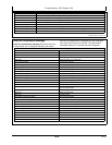
020
1.5 v Regulated Power Supply Voltage
021
3.3 v Regulated Power Supply Voltage
022
5.0 v Regulated Power Supply Voltage
023
Radar Input Status
024
Implement Switch Status
025 External Analog Input Voltage
026
Compact Flash Drive Status
028
CCD Bus - Bus Status
029
CCD Bus - Positive Voltage
030
CCD Bus - Negative Voltage
031
Bezel Key Status
032
Real Time Clock (RTC)
033
Maximum Sleep Time
038
Synchronize Brightness
039 Daytime Luminance
040 Daytime Luminance Balance Ratio
041 Nighttime Luminance
042 Nighttime Luminance Balance Ratio
35-5
090811
PN=48