


C 4.74
Operating instructions
82 149 443
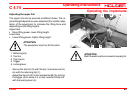
Operating the implements
2
3
4
6
1
5
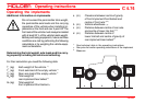
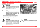
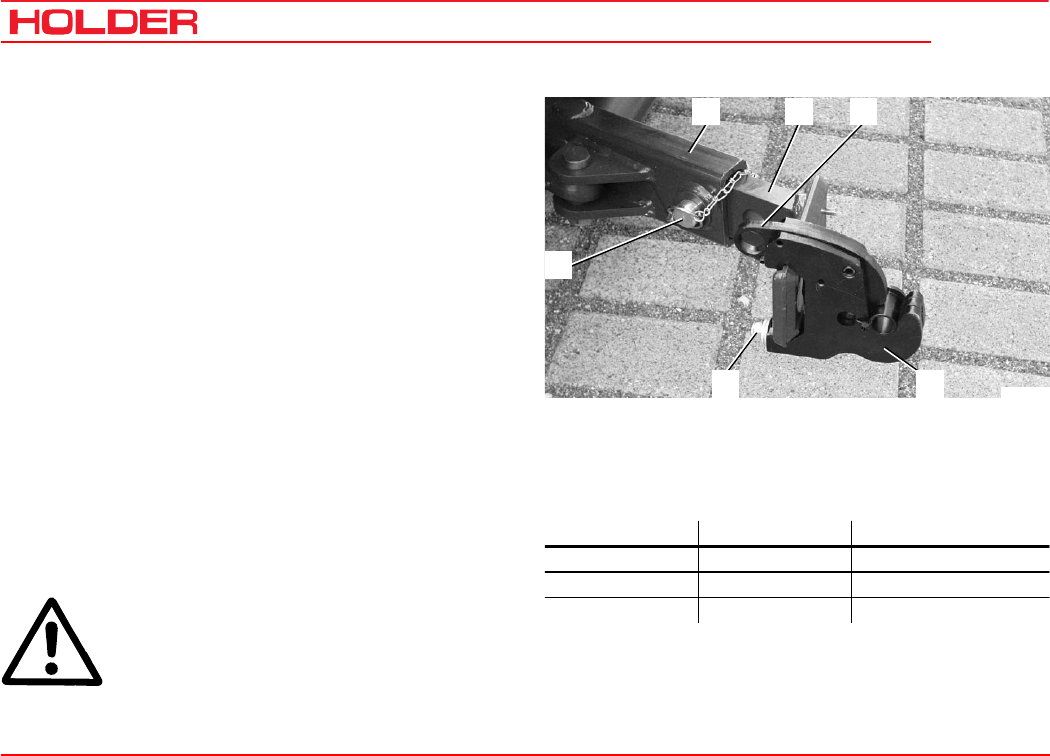
Bild_C233
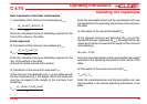
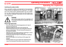
Adjusting the pintle hooks and pintle hook bars
You can adjust the pintle hooks laterally and longitudinally.
- Measure the stand-off of the pins on your implement.
- Loosen the clamping screws (6) on both sides.
- Slide the pintle hooks laterally until the required
distance is reached.
- Retighten the clamping screws.
- Equipment of category IIcan be attached with the
pintle hooks (5) directly.
- For equipment of category I install the reducing
sleeves on the left and right side.
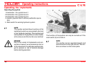
Adjusting the length of the pintle hook bar
- Loosen the 2 locknuts and clamping screws (inside
and at bottom) on the lower link (2).
- Pull the retaining clip out of the pin (1) and remove
the pin.
- You can put the pintle hook bar (3) in one of 3 posi-
tions.
- Insert the pin (1) in the hole and secure with the
retaining clip.
- Retighten the locknuts and clamping screws.
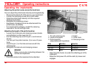
DANGER
Make sure no-one is standing between the
vehicle and implement.
- Drive the vehicle to the implement to be attached.
1 Pin with retaining clip 4 Catch
2 Lower link support 5 Pintle hook
3 Pintle hook bar 6 Clamping screw
(adjustable) with 3 positions
- Steer the pintle hooks (5) under the attaching pin of the
implement.
- Raise the front power lift until the catch (4) closes and
engages.
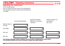
Hole Position Used for
1st hole Front Category I and II
2nd hole Centre Category I
3rd hole Rear Optional attachments