


5
www.chpower.com
GN5060, GN6575
Pre-Operation (Continued)
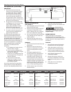
AUTO-IDLE CONTROL (IF EQUIPPED)
Some units have an auto-idle control
that idles the engine when there is no
demand required of the generator.
The control panel has an idle control
toggle switch to enable or disable this
function.
1. Idle Control Switch - ON enables
the auto-idle feature and the
engine will automatically idle when
not under load.
2. Idle Control Switch - OFF disables
the auto-idle feature and the
engine will run at full throttle.
LOW OIL SHUTDOWN
A low oil shutdown switch is provided
to protect the engine and generator
on most extended run models. When
engine oil level drops too low for
proper engine operation, the low oil
shutdown switch causes the engine
to shut off. If oil level is low when
attempting to start the generator
engine, the low oil level shutdown
switch prevents the engine from
starting. If engine does not start, check
oil level.
NOTE: It is important to keep the
generator unit on a level surface. The
oil level shutdown switch can prevent
the engine from starting even if oil level
is sufficient, when the generators unit is
placed on an uneven surface.
Operation
LOAD DEVICES
1. All load devices and extension cords
should use three prong terminals.
Refer to Table 2 for extension cord
and cable size requirements.
2. Allow the engine to run for 2-3
minutes before applying any
electrical loads.
manuals and product tags to determine
the wattage of all electrical load
devices.
If actual watt ratings are not available,
the Power Usage Chart, see Table 1, may
be used as a general guideline.
Remember that devices which generate
heat during operation such as heaters,
incandescent light bulbs, motors and
hair dryers have a higher power draw
than devices which generate little heat
during operation such as florescent
bulbs, radios, and clocks.
Long power cords and extension cords
also draw additional power. Keep cords
at minimum possible length.
Refer to Table 2 for maximum limits for
lengths of extension cords.
8. Circuit protection is provided by a
circuit breaker. The circuit breaker
opens when the generator load
exceeds its maximum capacity
or a short circuit occurs. If the
circuit breaker opens, perform the
following procedures to correct the
problem:
a. Shut off and disconnect all
electrical loads.
b. Attempt to determine the cause
of the electrical problem -
overloading or short circuit.
c. Do not use any devices that have
short circuits. Avoid overloading
the generator.
d. Press the circuit breaker
pushbutton to reset the circuit
breaker.
Repeated cycling of
the circuit
breaker indicates a problem and
may cause damage to the generator
or load devices. Do not operate the
generatoreated cycling of the circuit
breaker occurs.
3. The 120 volt receptacles are rated
for 20 amps and may be used in any
combination of 120 volt loads and
also with 240 volt loads through
the 240 volt receptacles.
The 240 volt receptacles, found
on some generators, are rated for
20 amps and may be used in any
combination of 240 volt loads and
also with 120 volt loads through
the 120 volt receptacles.
The 120/240 volt twist lock
receptacle is rated for 20 amps and
may be used in any combination of
120 volt and 240 volt loads.
4. Individual receptacles should not
be loaded beyond the amperage
rating.
5. Total combined load through
any combination of receptacle
must not exceed the rated load
limits of the generator. Refer to
the identification plate on the
generators for amp and wattage
specifications.
6. Always shut off and remove loads
before starting or shutting off the
generator engine.
7. When plugging multiple electrical
load devices into the generator
receptacles, be sure to connect and
activate the highest power draw
item first. Allow the generator
engine to stabilize, then connect
and activate the next highest power
draw device. The smallest power
draw device should be connected to
the receptacle and activated last.
NOTE: Power draw can be calculated
by multiplying volts and amps. The
resulting number is wattage.
Never exceed the posted maximum
wattage for the generator or any
individual receptacle. Refer to owner's
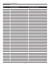
TABLE 2 - EXTENSION CORDS
Maximum Recommended Lengths (in feet)
Amps Watts 120 V Watts 240 V #8 Wire #10 Wire #12 Wire #14 Wire #16 Wire
2.5 300 600 1000 600 375 250
5 600 1200 500 300 200 125
7.5 900 1800 350 200 125 100
10 1200 2400 250 150 100 50
15 1800 3600 150 100 65
20 2400 4800 175 125 75 50
25 3000 6000 150 100 60
30 3600 7200 125 65
40 4800 9600 90