SECTION 5 MEASUREMENT
5.2 Measuring the 1-signal Selectivity
The 1-signal selectivity is measured when the receiver operates in a proportional region because the expected wave
and interference disturbing wave are fine. It is indicated by the relative input voltage rate required to equalize the
output of the receiver by connecting the signal generator to the receiver input pin in the expected wave receiving state
and changing its frequency to the expected or disturbing one. This method is available to measure a pass band width,
attenuation slope, and spurious response.
5.2.1 Measuring selectivity characteristics of the FM receiver in 20 dB NQ method
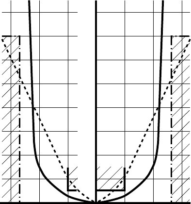
This figure shows the selectivity characteristics of a
signal-channel FM receiver 146 to 162 MHz. The
approved values are as follows:
• Pass band width ........6 dB (Reduction width = 20
kHz or more)
• Attenuation slope ......70 dB (Reduction band width =
50 kHz or less)
These conditions apply to measure the selectivity in the
20 dB NQ method as follows:
• Pass band width ........Increase the SG output by 6 dB
as compared with the NQ
sensitivity and move up or
down the frequency so that the
NQ sensitivity is obtained
again. Then, obtain this width
from its frequency width.
• Attenuation factor .....Increase the SG output by 60
dB, not 6 dB like the above.
• The characteristics curve must not be in the hatched part. The solid line is approved; the broken line is rejected.
80
70
60
50
40
30
20
10
6
10 20 3030 1020 +kHz–kHz


