


SECTION 1 GENERAL
1-11
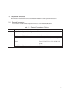
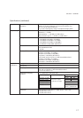
<Option>
Option 01 (Reference crystal oscillator)
Frequency 10MHz
Aging rate 5×10
-10
/day
±5×10
-9
(0 to 50°C)
Option 11 (Pulse modulator)
Frequency 0.125 to 2080MHz
On/Off ratio >80dB
Rise/Fall time <100ns
Min. pulse width <500ns
Pulse repetition frequency DC to 1MHz
Max. delay time <100ns
Overshoot/ringing <20%
Video feed through <20%
Pulse modulation signal External, rear-panel BNC connector, 50/600 Ω, TTL (positive logic)
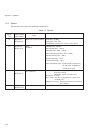
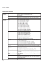
Option 21 (AF synthesizer)
Frequency 0.01Hz to 400kHz (sine wave)
0.01Hz to 50kHz (triangular wave, square wave, sawtooth wave)
Resolution 0.01Hz
Waveform Sine, triangular, square, sawtooth
Frequency accuracy Same as reference oscillator
Option 22 (FSK encoder)
Frequency shift amount: Shifts frequency depending on data state, as below.
(Data2
1
, Data2
0
)=(0, 0): -FM deviation set value
(Data2
1
, Data2
0
)=(0, 1): -FM deviation set value/3
(Data2
1
, Data2
0
)=(1, 0): +FM deviation set value
(Data2
1
, Data2
0
)=(1, 1): +FM deviation set value/3
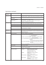
Setting frequency: Set frequency for data input in the following timing.
Free: Shift frequency at data input.
Rise Trig: Shift frequency at rising edge of external clock.
Fall Trig: Shift frequency at falling edge of external clock.
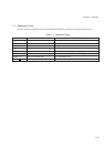
Baseband filter: Following filters can be used to pass signal.
Filter type: 10th-order Besser filter
Cutoff frequency: 100Hz to 30kHz(-3dB)
Set resolution: Upper 2 digits
FM deviation accuracy: Same as that of MG3641A/MG3642A, with restriction of no baseband filter (by-passed)
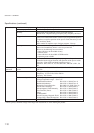
External modulation signal input
Data2
0
: Rear-panel BNC connector (Int Mod Cont 2)
TTL level, pull-down
Data2
1
: Rear-panel BNC connector (Int Mod Cont 1)
TTL level, pull-down
External clock signal input
Ext Clock: Rear-panel BNC connector (Int Mod Cont 3)
TTL level, pull-up