SECTION 8 CALIBRATION
8-3
(3) Setup
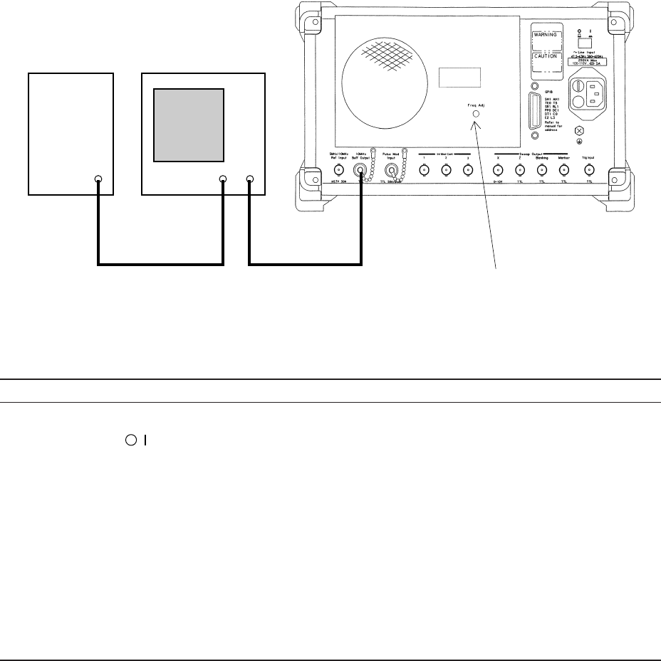
Fig. 8-1. Calibration of Reference Oscillator
(4) Calibration procedure
STEP PROCEDURE
1. Setup the device at room temperature 23 ±5°C. See Figure 8-1.
2. Set the switch on the rear panel to ON to preheat the MG3641A/MG3642A Reference oscillator and
hold this state for 24 hours.
3. After 24 hours lapsed, set the Stby/On switch on the front panel to ON.
4. Apply the standard frequency to the external synchronization input of the oscilloscope. Also apply
the output signal of the buffer output connector on the rear of the MG3641A/MG3642A to vertical axis
Y of the oscilloscope.
5. Adjust the oscilloscope so that the input waveform can be observed. If the input waveform on the
oscilloscope moves to the right or left and the synchronization is difficult, the frequency of the Refe-
rence oscillator does not match the standard.
6. The MG3641A/MG3642A is provided a Rererence oscillator calibration hole on the read. See Figure 8-
1. Turn the potentiometer in the hole so that the input waveform on the oscilloscope does not move to
the right or left.
Note
: If standard frequency 10 MHz is applied to axis X of the oscilloscope, a Lissajous’s waveform is generated.
In this case, adjust the frequency of the Reference oscillator in step 6 so that a static circle is drawn.
OUTPUT IN TRIG
IN
Buff Output
10 MHz
MG3641A/MG3642A rear panel
Frequency
standard
Oscilloscope
Reference oscillator frequency
adjustment hole
10 MHz/N
(N = Integer)