


SECTION 5 MEASUREMENT
5.3.2 Measuring the cross-modulation characteristics
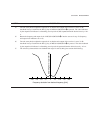
The cross-modulation characteristics are indicated by the input level of a disturbing level when the receiver output
obtained at detection of a disturbing modulation wave adjacent to an unmodulated expected-signal is lower than the
output obtained at detection only of the modulated desired-signal by a specific value, e.g., 20 dB.
NOTE
The cross-modulation occurs in the receiver as the desired signal modulated by the modulation signal of the
disturbing signal because the receiver operates non-linearly when the desired receiving signal is applied to the
receiver as well as a disturbing wave having a different higher-level modulated frequency.
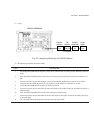
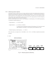
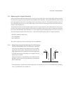
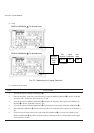
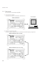
(1) Setup
The configuration is the same as that of the 2-signal selectivity above. However, this paragraph describes the AM
receiver.
To explain the measurement procedure, the desired wave is set to 1500 kHz and the disturbing wave is separated
from it by ±5 kHz × n.
(2) Measurement procedure
STEP PROCEDURE
1. Turn off the output of MG3641A/MG3642A .
2. Set the frequency of MG3641A/MG3642A to 1500 kHz.
3. Set the AM modulation of MG3641A/MG3642A to 30 % and internal modulation frequency to 400 Hz.
4. Synchronize the receiver with receiving frequency of 1500 kHz so that the indicator of the level meter
reaches the maximum, turn off the AGC of the receiver, then place the receiver into the appropriate state.
5. Adjust the output level of MG3641A/MG3642A so that the indicator of the level meter reaches the rated
signal output.
6. The value indicated by the output level indicator of MG3641A/MG3642A in step 5 is E
1
dB
µ
.
7. Turn off the modulation of MG3641A/MG3642A and turn on the output of MG3641A/MG3642A .
8. Set the frequency of MG3641A/MG3642A to 1500 kHz.
9. Set the output level of MG3641A/MG3642A to that of MG3641A/MG3642A , E
1
dB
µ
in step 6.
10. Set the AM modulation and modulation frequency of MG3641A/MG3642A to those of MG3641A/
MG3642A in step 3.
11. Change the output level of MG3641A/MG3642A and set the value of the output level indicator of
MG3641A/MG3642A to E2 dB
µ
when the receiver output is lower than the rated signal output set in step
5 by – 20 dB. (This is a cross-modulation characteristic when the disturbing wave is the same as the desired
frequency.) Then, set the level of the rated output –20 dB (1/10) to Vs dB.
12. Place MG3641A/MG3642A into the relative frequency display mode and relative level display mode,
then set the output level resolution to 1 dB.
13. Set the frequency step size of MG3641A/MG3642A to 5 kHz.