


SECTION 5 MEASUREMENT
STEP PROCEDURE
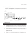
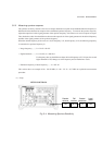
7. Turn on the output of MG3641A/MG3642A , place MG3641A/MG3642A into the relative level mode,
and set the output level resolution to 1 dB.
8. Set the frequency step size of MG3641A/MG3642A to 20 kHz.
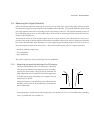
9. Turn the rotary knob to adjust the output level so that the noise output of the receiver is set to V
N
dB
obtained in step 2 each time the Edit [^] key of MG3641A/MG3642A is pressed. The value indicated by
the output level indicator is the disturbing input level separated from the desired wave by + ∆f × n.
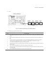
10. Return the frequency and output level of MG3641A/MG3642A in the state set in step 3 (frequency and
output level indicators set to +0).
11. Turn the rotary knob to adjust the output level so that the noise output of the receiver is set to V
N
dB
obtained in step 2 each time the Edit [ ] key of MG3641A/MG3642A is pressed. The value indicated by
the output level indicator is the disturbing input level separated from the desired wave by – ∆f × n.
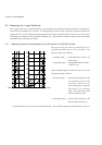
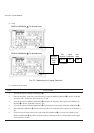
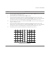
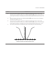
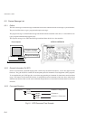
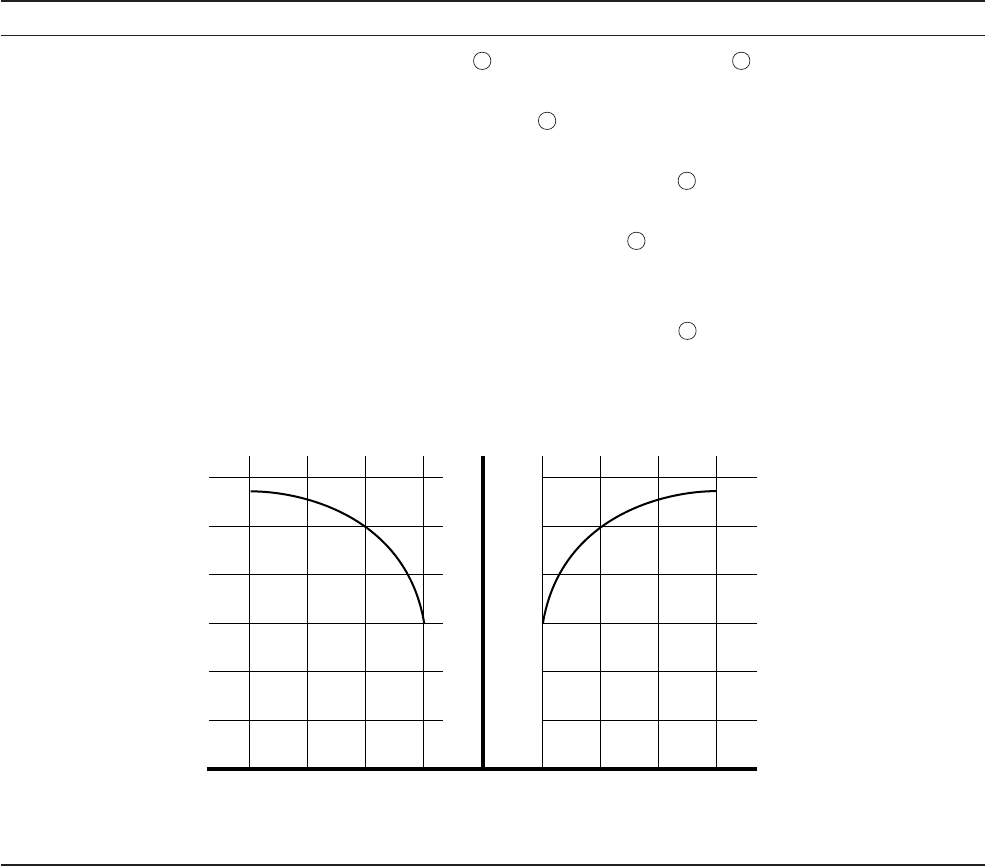
12. The following sensitivity suppression characteristics are obtained in steps 9 and 11:
>
80604020020406080
120
100
80
60
40
20
Disturbing wave input level (dB)
Disturbing frequency offset [kHz]