


SECTION 1 GENERAL
1-9
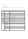
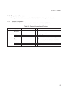
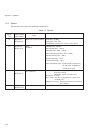
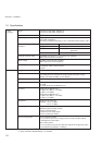
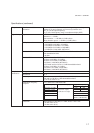
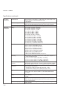
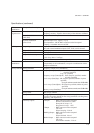
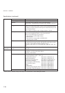
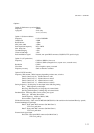
Specifications (continued)
Pulse See specifications of options.
modulation
Modulation Internal modulation (Int1) Frequency: 400 Hz/1 kHz (Switched over)
Frequency accuracy: Equal to the accuracy of the reference oscillator.
signal source
Internal modulation See specifications of options.
(Int2, Int3)
External modulation Optimum input level: Approx. 2 Vp–p
(Ext1, Ext2) Input impedance: 600 Ω, BNC connector on the front panel
Coupling: Switchable between AC/DC
AF Output Output signal source Any one out of the internal modulation signal sources (Int1, Int2,
Int3) and external modulation inputs (Ext1, Ext2) can be selected.
Output level 0 to 4 Vp–p
Output level resolution 1 mVp–p
Output level accuracy In Source=Int1 1 kHz:
±(5% of set value + 2 mVp-p)
Impedance 600 Ω, BNC connector on the front panel
Simultaneous Simultaneous modulation, AM depth and FM deviation can be set
modulation independently for all combinations, except for a combination of AM
and pulse modulation.
Sweep function Sweep parameter Frequency, Output level, and Memory
Sweep pattern Frequency sweep (Start/Stop): Liner (Stepsize specified, number
of points specified)
Log (1 % specified)
Frequency sweep (Center/Span): Liner (Stepsize specified, number
of points specified)
Level sweep (Start/Stop): dB (Stepsize specified, number of points
specified)
Sweep in continuous mode (max. 20 dB width)
Level sweep (Center/Span): dB (Stepsize specified, number of points
specified)
Sweep in continuous mode (max. 20 dB width)
Memory sweep (Start/Stop)
Sweep mode Auto, Single, Manual
Sweep time Setting range 1 ms to 600 s/point, Resolution 10
µ
s/point
(Actual sweep time depends on the sweep parameter switching times,
frequency, and output level.)
Auxiliary outputs X-Output : BNC connector on the rear panel
Staircase sawtooth wave worm
Start point of sweep: 0 V
Stop point of sweep: +10 V
Z-Output : BNC connector on the rear panel
TTL level
When sweeping: H-level
Blanking-Output : BNC connector on the rear panel
TTL level
When switched: L-level
Marker-Output : BNC connector on the rear panel
TTL level
When marker matches: H-level