


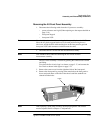
Replaceable Parts
Assembly and Disassembly Guidelines
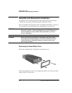
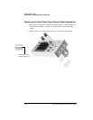
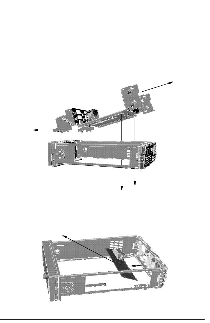
Agilent E4418B/E4419B Service Guide 5-11
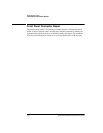
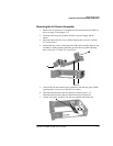
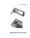
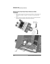
Removing the A4 Comms Assembly
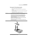
1. Remove the A2 processor, A5 daughter and A6 measurement assemblies as
shown on page 5-10 and page 5-12.
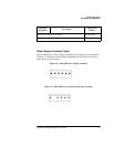
2. Disconnect the line power module from the A1 power supply and the
chassis.
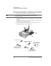
3. Disconnect the earth wire screw. (When replacing this screw use a 9 lb/in
T15 screw driver.)
4. Remove the two screws on the underside of the deck assembly. Remove the
assembly by sliding forward and tilting up from the rear (when replacing
these screws use a 21 lb/in T15 screw driver).
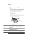
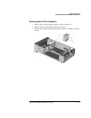
5. Unscrew the GP-IB and RS232/422 connectors from the rear panel. (When
replacing these screws use a 6 lb/in 9/32 in socket.)
6. Disconnect the Recorder cable for channel A from J23 pins 1,2,3.
Disconnect the Recorder cable for channel B from J23 pins 4,5,6.
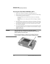
7. Lift the A4 Comms assembly from the two standoffs and slide it out.
screws