


Replaceable Parts
Assembly and Disassembly Guidelines
Agilent E4418B/E4419B Service Guide 5-9
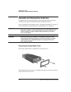
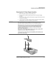
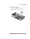
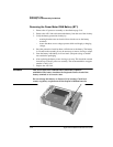
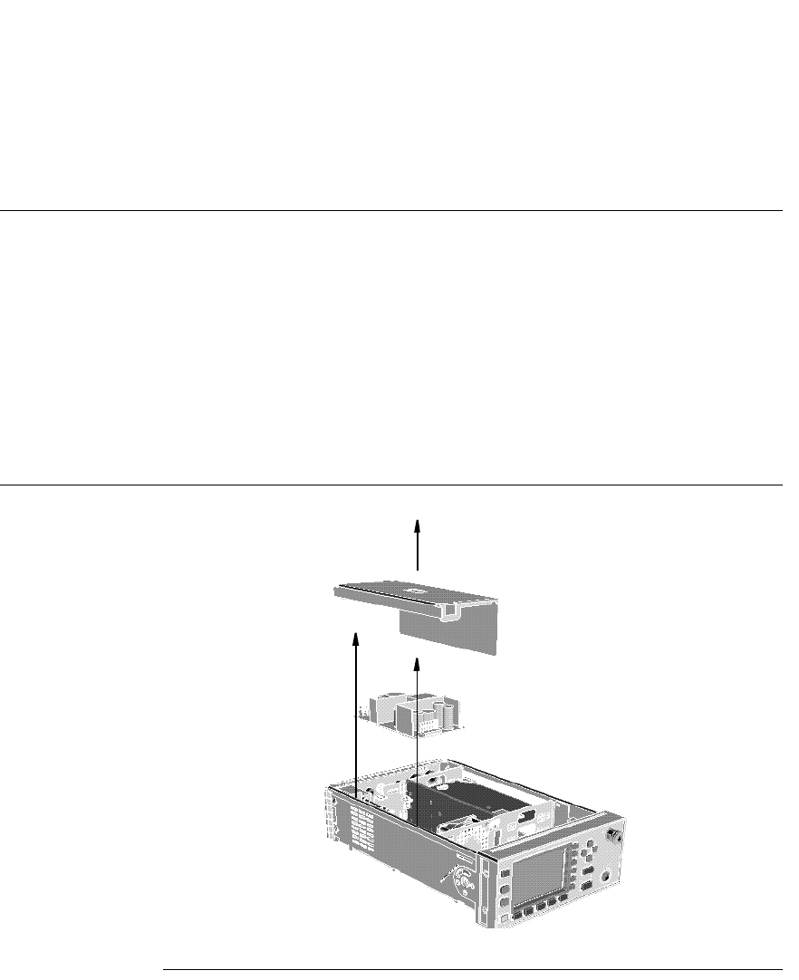
Removing the A1 Power Supply Assembly
1. Remove the power supply cover by lifting it out.
2. Disconnect the line input module from the chassis and power supply
assembly.
3. Disconnect the cable assembly from the power supply which connects to the
A2 processor assembly.
4. Unscrew the power supply assembly and lift out the power supply. (When
replacing these screws use a 9 lb/in T15 screw driver.)
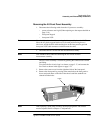
WARNING When replacing the power supply unit in the power meter ensure that
all earth wiring is reconnected. There are two terminals to check:
The first is the force fit connector to the power supply unit itself. It is
essential that the gap between the terminal and the adjacent large
capacitor is maximized. Fit the connector so that its flat side faces
towards the large capacitor.
The second, a closed loop terminal bonded to the chassis with an M3.5
machine screw (use a 9 lb/in T15 screw driver).
All the protective earth wiring can be identified by the insulation color
green with a yellow stripe.