


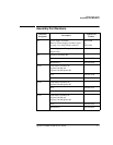
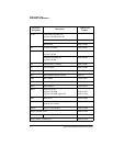
Replaceable Parts
Assembly and Disassembly Guidelines
5-10 Agilent E4418B/E4419B Service Guide
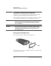
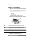
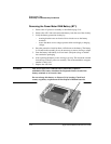
Removing the A2 Processor Assembly
1. Remove the A5 daughter and A6 measurement assemblies as described on
page 5-12.
2. Move the A2 plastic support bracket to its forward position using the two
side levers, unclip the flexi-cable retaining bar on the front panel keypad and
front panel LCD cable connectors and disconnect the cable.
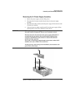
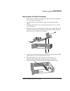
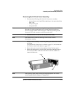
3. Disconnect the following cables from the A2 processor assembly:
n power reference semi-rigid
n fan connector
n power supply connector
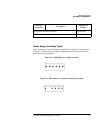
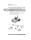
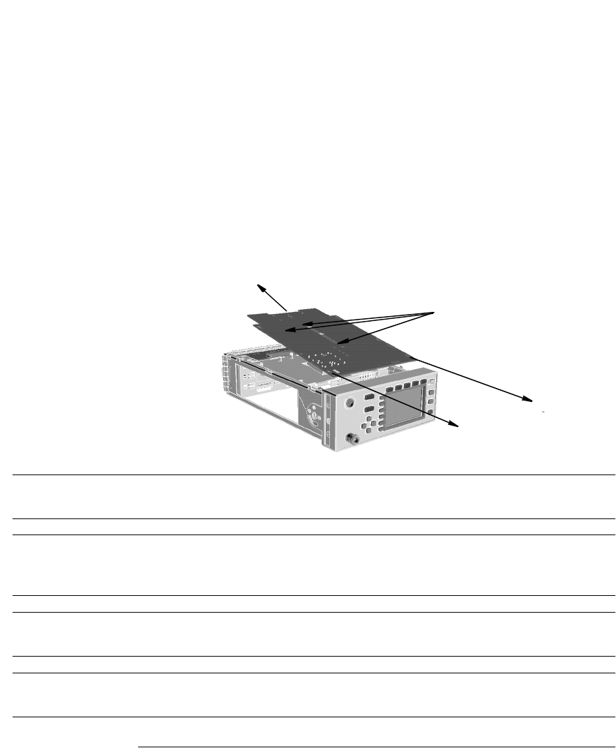
4. Turn the power meter upside down and remove the three screws as shown.
(When replacing these screws use a 6 lb/in T10 screw driver.)
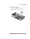
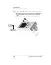
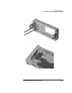
5. Push the A2 processor assembly towards the front panel to release it from
the 50-pin connector. Lift it upwards to remove.
Note When re-assembling the processor board, ensure the A2 plastic support
bracket is returned to its locked position.
Note After replacing a processor board, the Power Reference Frequency and
Level must be checked. For further information refer to “Performance
Tests”, on page 2-1.
Note After replacing a processor board, the display brightness and contrast must
be adjusted. See “Adjustments”, on page 3-1.
Note Firmware should be downloaded to the instrument after the processor board
is replaced. Refer to “Downloading Firmware”, on page 5-7.
screws