


Performance Tests
Power Reference Level Test
2-18 Agilent E4418B/E4419B Service Guide
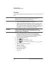
4. Preset the power meter:
Press , then on the power meter.
Set the Agilent 432A RANGE switch to Coarse Zero. Adjust the front
panel Coarse Zero control to obtain a zero meter indication.
5. Zero the Agilent 432A test power meter:
•Fine zero the Agilent 432A on the most sensitive range.
•Set the RANGE switch to 1 mW.
6. Set the DVM to measure microvolts.
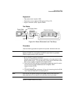
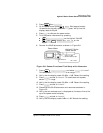
7. Connect the positive and negative input leads to the V
comp
and V
RF
connectors respectively, on the rear panel of the test power meter.
8. Observe the reading on the DVM. If less than 400 µV, proceed to the
next step. If 400 µV or greater, press and hold the test power meter
Fine Zero switch and adjust the Coarse Zero control so that the DVM
indicates 200 µV or less. Release the Fine Zero switch and proceed to
the next step.
9. Round the DVM reading to two decimal places.
Record this reading as V
0
.
•V
0
___________
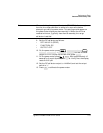
10.Turn the power reference on:
Press , .
11.Round the DVM reading to two decimal places.
Record this reading as V
1
.
•V
1
___________
12.Disconnect the DVM negative input lead from the V
RF
connector on the
Agilent 432A. Reconnect it to the Agilent 432A chassis ground.
13.Observe the DVM reading. Record the reading as V
comp
.
•V
comp
__________
14.Calculate the Power Reference Oscillator power using equation 2-4.
15.Verify that P
meas
is within the limits shown in Table 2-5 and record the
reading in the table.
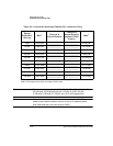
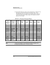
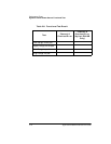
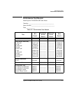
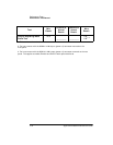
Table 2-5: Power Reference Level Test Result
Min Max Actual Result
0.999 mW 1.001 mW ________________
Preset
Local
Confirm
Zero
Cal
Power Ref O
n