


Theory of Operation
A1 Power Supply/Battery Charger
Agilent E4418B/E4419B Service Guide 4-3
A1 Power Supply/Battery Charger
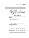
The A1 power supply/battery charger is a 20 W, 47 to 440 Hz switching
power supply producing three dc voltages, (+5 V, +12 V, -12 V) used to
power the subassemblies, and a constant current supply to recharge the
optional +12 V rechargeable Battery Module (Agilent Part Number
E9287A) when operating from an ac power source. The power supply can
be driven either by AC power voltages in the range 85 to 264 V or by the
A8 Rechargeable Battery Module.
The signal line Power_on, from the A2 processor assembly to the A1 power
supply assembly, indicates the status of the front panel POWER switch.
This signal line enables and disables the dc voltage outputs of the power
supply assembly to the A2 processor assembly when driven by the A8
battery assembly. The charging current for the rechargeable battery
module is independent of the state of the Power_on line.
A logic low on the Power_on line indicates that the front panel POWER
switch is in standby mode and the three dc voltage outputs from the power
supply are disabled. A logic high on this line indicates that the POWER
switch is in the On mode and the three dc voltages from the power supply
are enabled. Power is distributed to the meter subassemblies via the
processor assembly (See “A2 Processor Assembly”, on page 4-4).
If fitted, the A8 rechargeable battery module controls the charging current
while ac power is connected to the meter.The fan assembly is active under
the following conditions:
1. ac power connected and the POWER switch set to On.
or
2. ac power connected, POWER switch set to Standby and optional
+12 V rechargeable battery module fitted.
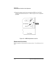
The ac line fuse is located in the line input module on the power meter’s
rear panel (Agilent Part Number 2110-0957). The fuse holder contains a
spare fuse as standard on shipment.