


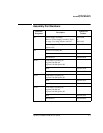

Theory of Operation
A6 Measurement Assembly
Agilent E4418B/E4419B Service Guide 4-11
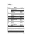
The DSP chip controls the logic which sets the chopper driver voltage and
frequency control. For the:
• Agilent 8480 series power sensors this is 0 V and -10 V at 217 Hz.
• Agilent E-series power sensors this is +7 V and -3 V at 434 Hz.
The DSP also controls logic to allow the AUX ADC to measure a number of
voltages, and when requested, send the relevant data to the host
processor. The AUX ADC digitizes a voltage which is produced by the
Agilent E-series power sensors and is proportional to temperature. This
voltage is required for temperature compensation. This AUX ADC also
tests the sensor resistor wires to check sensor continuity. Lastly, use is
made of this AUX ADC for the power meter’s self test of both the
measurement assembly and the A2 processor assembly. The results are
reported back to the A2 processor assembly via the “Internal Serial Bus”.
The Agilent E-series power sensors have built in serial EEPROM and
range switching which is controlled or accessed via the measurement
assembly. The “N-Chop” sensor wire used by the Agilent 8480 series power
sensors doubles as a serial clock and the sensor resistor line doubles as a
bi-directional serial data line. The “Auto Zero” line is also used as a serial
bus enable control.
The wire labelled “Auto Zero” is grounded to the “Sensor Ground” line
when an Agilent 8480 series power sensor is used. Autozeroing is
accomplished without the need for this signal in the power meter.
All clocks are derived from the 16.67 MHz system clock which is generated
on the A2 processor assembly and distributed on the A5 daughter
assembly.