


Troubleshooting
Introduction
6-2 Agilent E4418B/E4419B Service Guide
Introduction
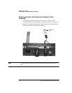
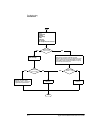
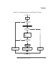
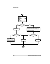
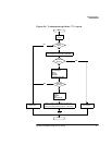
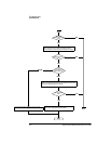
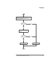
This chapter enables qualified service personnel to diagnose suspected
faults with the power meter Rmt I/O (Remote Input/Output) signal lines
and RS232/422 serial port.
If there is a problem when attempting to use the RS232/422 serial
interface or the remote I/O functions, consult the User’s Guide and
confirm that all the user setups are correct before proceeding with the
following fault finding flow charts.
Suggested Diagnostic Equipment
1. Digital multi-meter capable of measuring voltage and resistance,
for example, Agilent E4975.
2. Signal source capable of producing 300 ms TTL single shot pulses,
for example, Agilent 33120A.
3. +5 V TTL logic level source.
4. RS232 self test connector - 9 way ‘D’ type female connector with
the following pins wired together:
Pin 2 (Rx) to Pin 3 (Tx)
Pin 4 (DTR) to Pin 6 (DSR)
Pin 7 (RTS) to Pin 8 (CTS)
5. RS422 self test connector - 9 way ‘D’ type female connector with
the following pins wired together:
Pin 1 (CTS-) to Pin 9 (RTS-)
Pin2 (Rx-) to Pin 4 (Tx-)
Pin 3 (Tx+) to Pin6 (Rx+)
Pin7 (RTS+) to Pin 8 (CTS+)
6. 8 way RJ45 plug with flying leads wired to pins 2, 3, 4, 5 and 6 to
apply and monitor signals on the remote TTL I/O connector.
7. HP-IB controller and cable - required to apply “*RST” command
through the rear panel GP-IB connector.
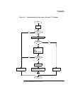
Note In the following flowcharts a bold font indicates the label of a
soft/hard key the user must select.