


Calibration 75
6
Calibration
Introduction
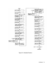
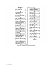
This chapter describes the calibration procedures for the Electronic Load and gives a sample calibration program. The
Electronic Load should be calibrated annually, or whenever certain repairs are made (refer to the Service Manual).
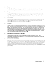
Calibration is accomplished entirely in software by sending calibration constants to the Electronic Load via the GPIB. This
means that the Electronic Load can be calibrated without removing its cover, or removing it from its cabinet if rack
mounted.
There are three DACs in the Electronic Load that must be calibrated - a main DAC, a readback DAC, and a transient level
DAC. Six ranges must be calibrated for both the main DAC and the transient DAC - a voltage range, a low resistance range,
a middle resistance range, a high resistance range, a low current range, and a high current range. The main DAC requires
two operating points to be calibrated for each range - a high point and a low point. The transient DAC requires only the
high operating point to be calibrated for each range; it uses the same low operating point as the main DAC. Note that the
transient level for the middle and high resistance ranges is lower than the high level of the main DAC.
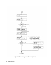
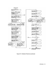
The readback DAC is only calibrated for the high current range and the voltage range. It also requires two operating points
to be calibrated for each range - a high point and a low point. For the sake of convenience you can use the same values to
calibrate the main and the readback DAC, but you could also use different values to optimize accuracy.
Note All calibration must be done when the Electronic Load is at room temperature.
Example Programs
The example programs in this chapter are written using the, Agilent BASIC Language. If you are using an HP Series
200/300 computer, simply type in the programs and run them. At appropriate places in the program you will be prompted to
measure and enter values into the computer and verify that the values are within specifications.
If you are using a different computer or programming language, you will have to modify the programs before you can run
them.
Equipment Required
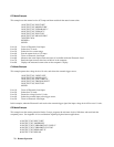
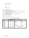
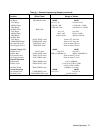
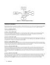
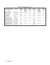
Table 6-1 lists the equipment required for calibration. Note that less accurate and less expensive current shunts may be used
than those listed, but the accuracy to which current and resistance programming as well as readback, can be checked must be
reduced accordingly. Figure 6-1 illustrates how the calibration equipment should be connected.
Table 6-1. Equipment Required for Calibration
Equipment Characteristics Recommended Model
Shunts
0.1 Ω @ 15 A, 0.04% @ 25 W
Guildline 9230/15
0.01 Ω @ 100 A, 0.04% @ 100 W
Guildline 9230/100
Voltmeter dc accuracy of 0.01%, 6 digit readout Agilent 3456A or equivalent
Power Supply 240 Vdc/60 Adc minimum
PARD < 3 mV rms/30 mv pp
Agilent 6032A or Agilent 6035A and
Agilent 6031A, or equivalent
Controller GPIB (IEEE-488) Agilent BASIC (5.0/5.1)