


20 Operation Overview
Local/Remote Control
Local (front panel) control is in effect immediately after power is applied. The front panel keypad and display allow manual
control when the Electronic Load is used in bench test applications. Remote (computer) control goes into effect (front panel
Rmt annunciator is on) as soon as the Electronic Load receives a command via the GPIB. A built-in GPIB interface and
HPSL compatible commands allow control and readback of all functions when the Electronic Load is used in computer
controlled applications.
With remote control in effect, only the computer can control the Electronic Load; the front panel keypad has no effect. You
can, however, still use the front panel display to view the input voltage and current readings. You can return the Electronic
Load to local control from remote control by pressing
. This will return the Electronic Load to local control, unless
the local-lockout command has been received from the GPIB computer.
Details of local operation are covered in Chapter 4 and fundamentals of remote programming are given in Chapter 5.
Complete HPSL programming details are given in the Programming Reference Guide. The remaining paragraphs in this
chapter describe the operating modes, transient operation, protection features, and other operating features of the Electronic
Load.
Programmable Features
Modes of Operation
The three modes of operation are:
•
constant current (CC)
•
constant voltage (CV)
•
constant resistance (CR)
When programmed to a mode, the Electronic Load remains in that mode until the mode is changed or until a fault condition,
such as an overpower or overtemperature, occurs. When changing modes, the load’s input is disabled for approximately 6
milliseconds (non-conducting state) before the new mode is enabled. This insures that there will be minimum overshoots
when changing modes.
The current, resistance, and voltage mode parameters described in subsequent paragraphs can be programmed whether or
not the mode is presently selected. When a mode is selected via the front panel or via the GPIB, most of the associated
parameters will take effect at the input (exceptions are noted in the mode descriptions).
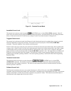
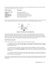
Constant Current CC (Mode)
In this mode, the load will sink a current in accordance with the programmed value regardless of the input voltage (see
Figure 2-1). The CC mode can be set with front panel keys(
, , and ) or via the GPIB
(MODE:CURR command). The CC mode parameters are discussed in the following paragraphs.
Ranges
Current may be programmed in either of two overlapping ranges, a low range and a high range. The low range provides
better resolution at low current settings. The range can be set at the front panel (
,
and ENTRY keys) or via
the GPIB (CURR:RANG command). Any value in the low range selects the low range. Any value above the maximum of
the low range selects the high range. Changing the range affects the load in the same manner as changing modes; i.e., it
causes the input to go through a non-conducting state for approximately 0.2 milliseconds. Note that the values of the
present current settings may be automatically adjusted to fit the new range. For example, if 10 A is the present setting and
the 0 to 6 A range is then programmed, the current setting will automatically be changed to 6 A; see Chapter 4.