Operation Overview 27
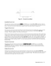
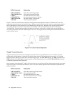
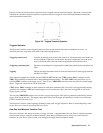
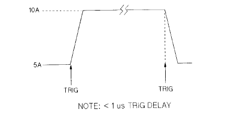
Figure 2-6 shows the waveform that would result for this toggled transient operation example. Operation is similar to that
described for continuous and pulse operation, except that each time a trigger is received the input alternates between the
main and transient current levels.
Figure 2-6. Toggled Transient Operation
Triggered Operation
The Electronic Load has various triggering modes to allow synchronization with other test equipment or events. As
described previously, triggering can be used for the following applications:
Triggering a preset level
Transfers all pending preset levels to the actual level. For the presently active mode, the
new level appears at the input. For the modes which are not presently active, the preset
levels will not take effect at the input until the applicable mode becomes active.
Triggering a transient pulse
Generates a transient pulse of programmable width when pulsed transient operation is in
effect.
Toggling
Changes the input between the main level and the transient level when toggled transient
operation is in effect.
Three triggering methods are available over the GPIB: the GET function, the *TRG common HPSL command, and the
TRIG subsystem HPSL command (refer to Programming Reference Guide). The HPSL TRIG subsystem allows you to
select the TRIG command as the trigger source. There is also a TRIGGER connector on the rear panel for external trigger
inputs. Triggering cannot be done via the front panel.
*TRG and the TRIG command are both synchronous with other commands; that is, the load is not triggered until pending
operations are completed. GET and external triggers are all asynchronous; that is, the loads are triggered as soon as the
trigger signal is received.
The rear-panel TRIGGER connector also provides a trigger output signal. This signal is generated synchronously with the
trigger signal sent by the load. The trigger output signal can be used to trigger an external device such as an oscilloscope,
DVM, or another Electronic Load.
The Electronic Load has a status reporting capability to keep track of trigger operations. Refer to ’Status Reporting’ in the
Agilent Electronic Loads Programming Reference Guide.
Slew Rate And Minimum Transition Time
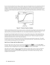
Slew rate is defined as the change in current or voltage over time. A programmable slew rate allows a controlled transition
from one load setting to another to minimize induced voltage drops on inductive power wiring, or to control induced
transients on a test device (such as would occur during power supply transient response testing).


