


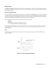

Installation 41
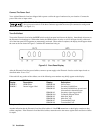
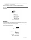
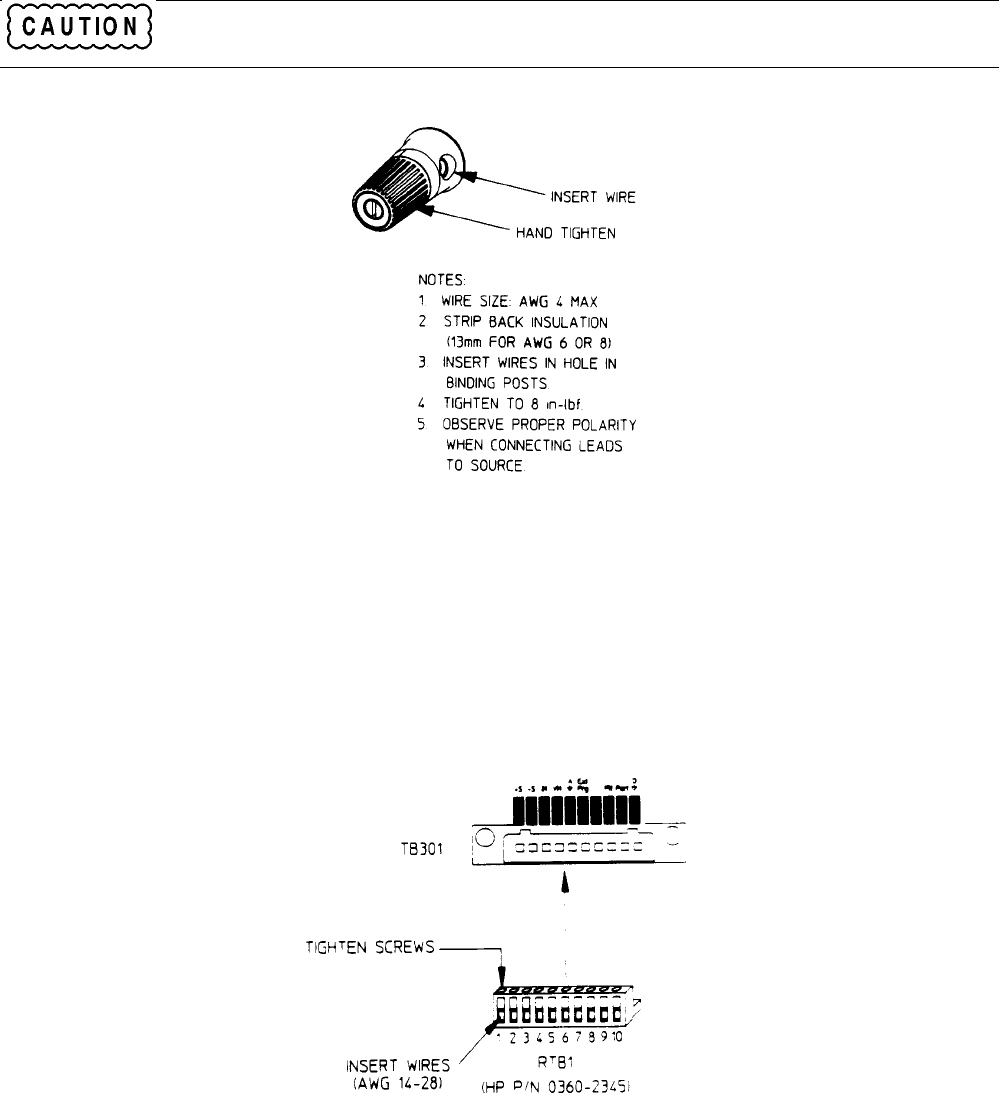
3. Hand tighten the adjustment knob to secure the wire in the binding post. If you are using a slotted screwdriver,
tighten the knob to 8 in.-lbf for a secure connection.
Installation for the optional front panel binding posts is the same as for the rear terminal binding posts.
Do not use lubricants or contact cleaners on the binding posts. Certain chemical agents can damage the
LEXAN material of the binding post, causing the part to fail.
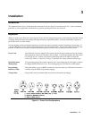
Figure 3-8. Input Binding Post
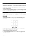
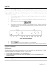
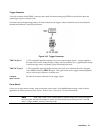
Control Connector
A ten-pin terminal block (TB301) connector and a quick-disconnect mating plug (RTB1) are provided for connecting
remote sense leads, external V/I monitors, an external programming input, and external control lines (see Figure 3-9). You
must remove the safety cover before you can disconnect mating plug RTB1.
Consistent with good engineering practice, all leads connected to the control connector should be twisted and shielded to
maintain the instrument’s specified performance.
Figure 3-9. Control Connector