


32 Operation Overview
If the software overcurrent limit is exceeded and persists beyond the specified delay time, the input is turned off. Also, for
these conditions, the OC and PS (protection shutdown) status register bits are set and will remain set until the OC condition
is removed and the bits are reset as previously described.
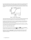
Overpower
Nominal Power Limit. The nominal power-limit boundary is set by software that monitors the input current and voltage.
If the input power exceeds the nominal power limit, the load sets the overpower status bit, which will reset if the overpower
condition ceases. If the overpower condition persists for 50 ms, the input turns off, and the OP and PS status bits are both
latched on. The input remains off, and the OP and PS status bits remain set, until protection clear occurs. Of course, if the
overpower condition is not corrected, the input will turn off again.
Overtemperature
The Electronic Load has an overtemperature (OT) protection circuit that turns off the input if the internal temperature
exceeds safe limits. If the OT circuit activates, the OT and PS status register bits are set and will remain set until they are
reset. If the OT condition still exists when the reset is executed, the input will remain off. You must wait until the load
cools down before you can reset the OT circuit. The fan will continue to operate to cool the unit as quickly as possible.
Reverse Voltage
This feature protects the Electronic Load in case the input dc voltage lines are connected with the
wrong polarity. If a reverse voltage (RV) condition is detected, turn off power to the dc source and the
load and make the correct connections.
The Electronic Load conducts reverse current when the polarity of the DC source connection is incorrect. The maximum
safe reverse current is specified in Table 1-1. The reverse voltage (RV) and voltage fault (VF) bits in the status register are
set when reverse voltage is applied. When the reverse voltage is removed the RV bit is cleared. However, the VF bit
remains set until it is reset. As previously described, the Fault output signal at the control connector tracks the state of the
VF bit. The Fault signal can be used to control an external relay in order to disconnect the load from the dc source if an
RV condition occurs.
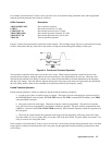
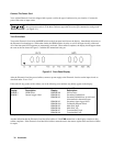
Control Connector
The Electronic Load has a 10-pin connector mounted on its rear panel. The connector signals are described in the following
paragraphs. See Chapter 3 for connection details.
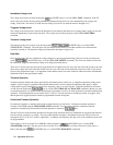
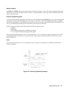
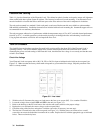
Remote Sensing
The remote sensing inputs, + S and - S, can be used in CV or CR modes. By eliminating the effect of the inevitable voltage
drop in the load leads, remote sensing provides greater accuracy by allowing the load to regulate directly at the source’s
output terminals, as well as measure the voltage there.