


3-24
Triggering the Oscilloscope
To use I2C triggering
To use I
2
C triggering
An I
2
C (Inter-IC bus) trigger setup consists of connecting the oscilloscope to
the serial data (SDA) line and the serial clock (SCL) line, then triggering on a
stop/start condition, a restart, a missing acknowledge, an EEPROM data read,
or on a read/write frame with a specific device address and data value.
1Press the More key in the Trigger section of the front panel, rotate the
Entry knob until
I
2
C is displayed in the Trigger softkey, then press the
Settings softkey to display the I
2
C trigger menu.
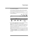
2 Connect an oscilloscope channel to the SCL (serial clock) line in the
circuit under test, then set the
SCL clock channel softkey to that channel.
As you press the SCL softkey (or rotate the Entry knob on mixed-signal
oscilloscopes), the SCL label for the source channel is automatically set and the
channel you select is shown in the upper-right corner of the display next to
"I
2
C".
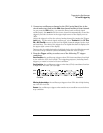
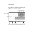
Adjust the trigger level for the selected analog channel by turning the Trigger
Level knob. For the mixed-signal oscilloscope, select Threshold in the D7 Thru
D0 or D15 Thru D8 menu to set the level for digital channels assigned to the clock
and data lines. The value of the trigger level or digital threshold is displayed in
the upper-right corner of the display.
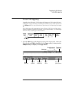
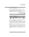
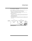
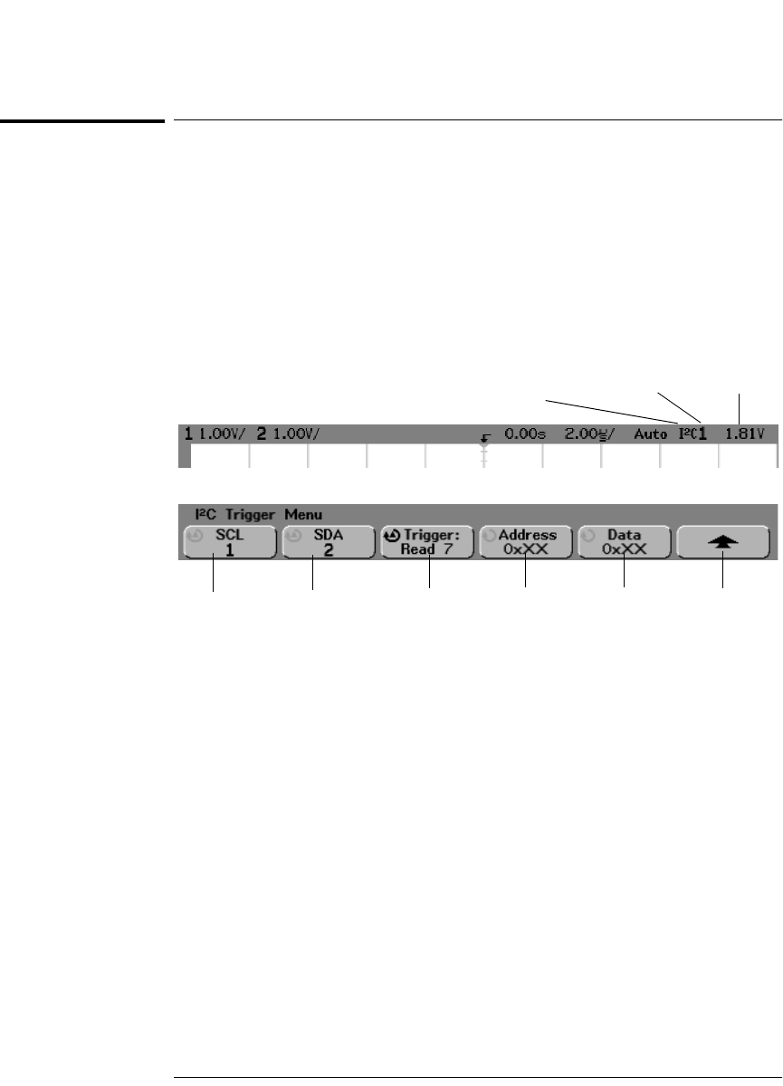
SCL Clock
channel
SDA Data
channel
Trigger on:
condition
Data
value
Trigger level
or threshold
Currently selected Clock
or Data channel
I
2
C trigger
Return to
previous menu
Address