


3-39
Triggering the Oscilloscope
To use SPI triggering
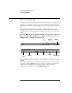
5Press the Frame by softkey to select a framing signal that the oscilloscope
will use for determining which clock edge is the first clock edge in the
serial stream.
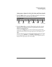
You can set the oscilloscope to trigger during a high chip select (CS), a low chip
select (~CS), or after a Timeout period during which the clock signal has been
idle.
• If the framing signal is set co CS, the first clock edge as defined (rising or
falling) seen after the CS signal transitions from low to high is the first clock
in the serial stream.
• If the framing signal is set to ~CS, the first clock edge as defined (rising or
falling) seen after the ~CS signal transitions from high to low is the first clock
in the serial stream.
• If the framing signal is set to Timeout, the oscilloscope generates it’s own
internal framing signal after it sees inactivity on the serial clock line.
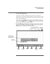
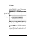
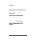
Timeout Select Timeout in t he Frame by softkey, then select the Timeout so ftkey
and turn the Entry knob to set the minimum time that the Clock signal must be
idle (not transitioning) before the oscilloscope will search for the Data pattern
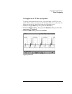
on which to trigger. When you press the Frame by softkey, the graphic shown on
the previous page changes to show timeout selection or the current state of the
chip select signal.
The Timeout value can be set anywhere from 500 ns to 10 s.
Chip Select Press the CS or ~CS softkey or turn the Entry knob to select the
channel that is connected to the SPI frame line. The label (~CS or CS) for the
source channel is automatically set. The data pattern and the clock transition
must occur during the time when the framing signal is valid. The framing signal
must be valid for the entire data pattern.
As you press the CS or ~CS softkey (or rotate the Entry knob on mixed-signal
oscilloscopes), the CS or ~CS label for the source channel is automatically set
and the channel you select is shown in the upper-right corner of the display
next to "SPI". When you press the Frame by softkey, the graphic shown on the
previous page changes to show timeout selection or the current state of the chip
select signal.
Adjust the trigger level for the selected analog channel by turning the Trigger
Level knob. Select Threshold in the D7 Thru D0 or D15 Thru D8 menu to set the
level for digital channels. The value of the trigger level or digital threshold is
displayed in the upper-right corner of the display.