


4-40
MegaZoom Concepts and Oscilloscope Operation
Using Digital Channels to Probe Circuits
Probe Grounding
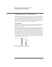
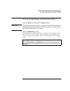
A probe ground is the low-impedance path for current to return to the source
from the probe. Increased length in this path will, at high frequencies, create
large common mode voltages at the probe input. The voltage generated behaves
as if this path were an inductor according to the equation:
Increasing the ground inductance (L), increasing the current (di) or decreasing
the transition time (dt), will all result in increasing the voltage (V). When this
voltage exceeds the threshold voltage defined in the oscilloscope, a false data
measurement will occur.
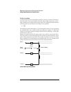
Sharing one probe ground with many probes forces all the current that flows
into each probe to return through the same common ground inductance of the
probe whose ground return is used. The result is increased current (di) in the
above equation, and, depending on the transition time (dt), the common mode
voltage may increase to a level that causes false data generation.
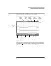
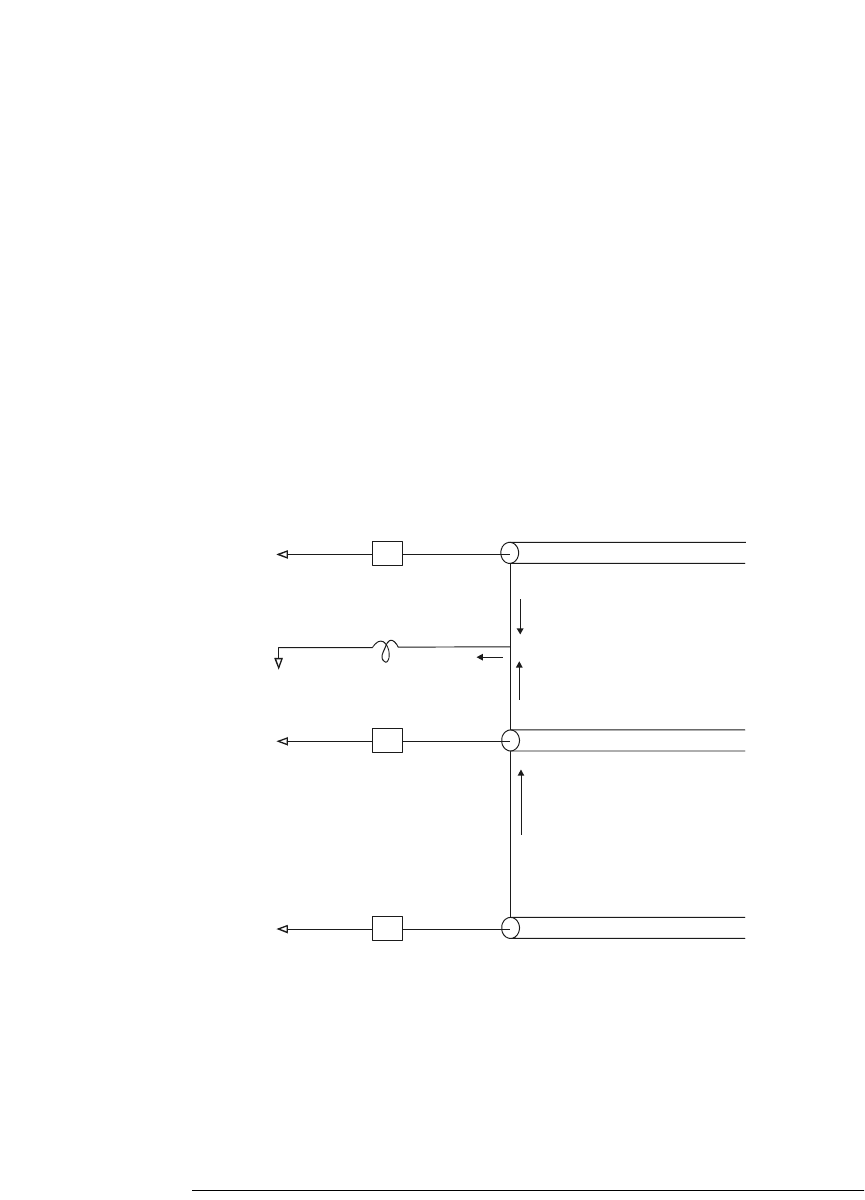
Common Mode Input Voltage Model
VL
di
dt
-----
=
Z
in
Z
in
i
n
i
2
+i
2
i
1
i
1
+i
n
+i
n
Z
in
Probe 1
L (GND)
Probe 2
Probe N
V
n
(Common Mode)
Probe
Ground