


4-9
MegaZoom Concepts and Oscilloscope Operation
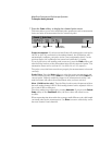
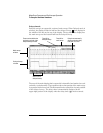
To setup the Analog channels
3Press the Imped (impedance) softkey
The 54620-series oscilloscope analog channel input impedance is always 1 MΩ.
The 54640-series oscilloscope analog channel input impedance can be set to
either 1M Ohm or 50 Ohm by pressing the Imped softkey.
• 50 Ohm mode matches 50-ohm cables commonly used in making high
frequency measurements. This impedance matching gives you the most
accurate measurements since reflections are minimized along the signal
path.
• 1M Ohm mode is for use with probes and for general-purpose measurements.
The higher impedance minimizes the loading effect of the oscilloscope on
the circuit under test.
When you connect an AutoProbe self-sensing probe, the oscilloscope will
automatically configure your probe to the correct impedance.
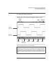
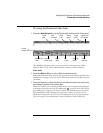
4Press the BW Limit softkey to turn on bandwidth limiting.
Pressing the BW Limit softkey turn s the bandwidth limit on or off for the selected
channel. When bandwidth limit is on, the maximum bandwidth for the channel
is approximately 20 MHz for 54620-series and 25 MHz for 54640-series. For
waveforms with frequencies below this, turning bandwidth limit on removes
unwanted high frequency noise from the waveform. Bandwidth limit also limits
the trigger signal path if the channel you are configuring is the trigger source.
When BW Limit is selected, “BW” is illuminated on the front panel next to the
channel position knob ( ).
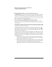
5Press the Vernier softkey to turn on vernier for the selected channel.
When Vernier is selected, you can change the channel sensitivity in smaller
increments with the volts/division knob. The channel sensitivity remains fully
calibrated when Vernier is on. The vernier value is displayed in the status line
at the top of the display.
When Vernier is turned off, turning the volts/division knob changes the channel
sensitivity in a 1-2-5 step sequence.
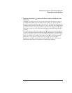
6Press the Invert softkey to inverted the selected channel.
When Invert is selected, the voltage values of the displayed waveform are
inverted. Invert affects how a channel is displayed, but does not affect
triggering. If the oscilloscope is set to trigger on a rising edge, it remains set to
trigger on a same edge (triggers at the same point on the waveform) after the
channel is inverted.
Inverting a channel will also change the result of any function selected in the
Math menu or any measurement.