


Operation 9
MAN0160 (Rev. 2/22/2006)
OPERATION
Never allow children or untrained persons to
operate equipment.
Do not allow bystanders in the area when oper-
ating, attaching, removing, assembling, or servic-
ing equipment.
Before working underneath, read manual
instructions, securely block up, and check stability.
Secure blocking prevents equipment from drop-
ping due to hydraulic leak down, hydraulic system
failure, or mechanical component failure.
Never allow riders on power unit or attachment.
Keep all persons away from operator control
area while performing adjustments, service, or
maintenance.
Keep hands and body away from pressurized
lines. Use paper or cardboard, not hands or other
body parts to check for leaks. Wear safety goggles.
Hydraulic fluid under pressure can easily penetrate
skin and will cause serious injury or death.
Make sure that all operating and service person-
nel know that if hydraulic fluid penetrates skin, it
must be surgically removed as soon as possible by
a doctor familiar with this form of injury or gan-
grene, serious injury, or death will result. CON-
TACT A PHYSICIAN IMMEDIATELY IF FLUID
ENTERS SKIN OR EYES. DO NOT DELAY.
A minimum 20% of tractor and equipment
weight must be on the tractor front wheels when
attachments are in transport position. Without this
weight, tractor could tip over, causing personal
injury or death. The weight may be attained with a
loader, front wheel weights, ballast in tires or front
tractor weights. Weigh the tractor and equipment.
Do not estimate.
Always wear relatively tight and belted clothing
to avoid entanglement in moving parts. Wear
sturdy, rough-soled work shoes and protective
equipment for eyes, hair, hands, hearing, and head.
MOUNT BLADE TO TRACTOR
IMPORTANT
■ The RB750-4 & RB850-4 should be mounted on
tractors with a maximum horsepower rating of 100
hp (75 kW).
The Rear Blade is a 3-point Category 2 implement. It
will attach to ASAE standard Category 2 quick-attach-
ing coupler or on 3-point Category 3 tractor, using a
bushing kit.
NOTE: Only use on Category 3, 3-point hitch trac-
tor whose lower lift arms adjust to 32" (813 mm)
apart.
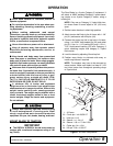
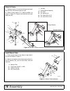
1. Set the tractor drawbar in short-high position.
2. Attach tractor draft links to the A-frame with 1-1/8"
pin (21) and secure with Klik pins (44).
3. Connect the tractor top link to top hole in A-frame,
using 1 x 4-29/32" heat-treated pin (20) and cotter
pin (31). Use 1 x 1-1/4" bushing (23) and 1-1/8 x 1-
7/16" heat-treated bushing (24) with Category 2
quick- attaching coupler and category 3, 3-point
hitch tractor.
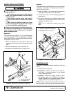
4. Level the boom by adjusting lift and top link.
5. Position sway blocks to eliminate side sway or
install sway braces if required.
NOTE: The drawbar may have to be removed on
some tractors. Make sure blade is at least 6" (152
mm) from tractor tires throughout operating range
of 3-point hitch.
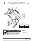
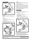
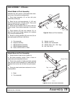
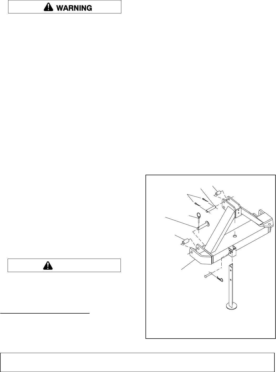
Figure 1. A-Frame Components
CAUTION
1
23
3
31
44
2
4
2
1
2
0
CD5979-1
1. A-Frame
20. Clevis pin 1 x 4-29/32 HT
21. Hitch pin 1-1/8
23. Sleeve 1 x 1-1/4 x 2
24. Sleeve 1-1/8 x 1-7/16 x 2-5/8
31. Cotter pin 1/4 x 1-3/4
44. Klik pin 7/16 x 11/32 HT