


Assembly 19
MAN0160 (Rev. 2/22/2006)
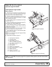
Models: MA, SA, & TA or Optional
Hydraulic Angle Kit 1004870
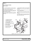
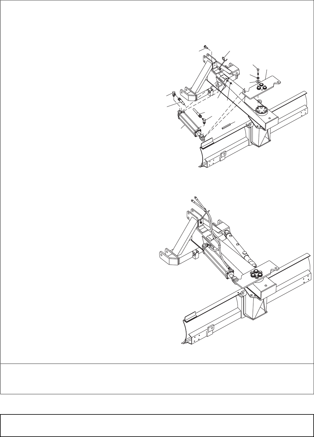
Install Hydraulic Angle Cylinder
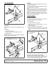
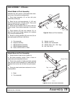
Refer to Figure 14.
1. Remove lock pin assembly (2) and safety pin (10)
from rear of boom, if previously installed. See Figure
13 on page 18 for lock pin assembly location.
2. Remove hardware and retaining cap (3) from top
of boom if previously installed. See Figure 13 on page
18 for retaining cap location.
3. Place hydraulic angle arm assembly (4) on boom
as shown Figure 14.
4. Secure into position using three cap screws (27),
lock washers (25), and flat washers (26).
5. Attach hydraulic cylinder (6) to boom and hydrau-
lic angle arm assembly as shown. Secure with pins
supplied with the cylinder.
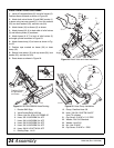
6. Attach hose holder (5) to A-Frame using carriage
bolt (24), flat washer (23), and lock nut (22).
7. Install adjustable elbows (7) and hoses (8) (Mod-
els MA and TA) to cylinder.
NOTE: Do not install 84” hoses (8) if Hydraulic Offset
cylinder is to be installed.
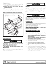
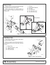
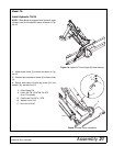
8. Route hoses as shown in Figure 15.
4. Hyd Angle Arm Assembly
5. Hyd Hose Holder
6. Hyd Cylinder 3-1/2 x 16
7. Elbow, 3/4 ORBM 3/4 JICM 90
8 Hose, 3/8 84 1/2 NPTM 3/4 JICF
9. Strap, Binding 14-1/2
22. Nut, Lock 3/8
23. Washer, Flat 3/8 Standard
24. Bolt, Carriage 3/8 NC x 1-1/4 GR1
25. Washer, Lock 3/4
26. Washer, Flat 3/4 SAE
27. Cap Screw, 3/4 NC x 3 GR5
Figure 14. Angle Kit Installation
Figure 15. Angle Kit Hose Routing
NOTE: For model SA, Proceed to page 22 for hydraulic offset cylinder and relief valve installa-
tion instructions.
8
7
6
7
8
9
23
22
27
25
26
4
24
5
CD5986
CD5998