


14 Assembly
MAN0160 (Rev. 2/22/2006)
ASSEMBLY
Before dismounting power unit or performing
any service or maintenance, follow these steps:
disengage power to equipment, lower the 3-point
hitch and all raised components to the ground,
operate valve levers to release any hydraulic
pressure, set parking brake, stop engine, remove
key, and unfasten seat belt.
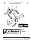
Before working underneath, read manual
instructions, securely block up, and check stabil-
ity. Secure blocking prevents equipment from
dropping due to hydraulic leak down, hydraulic
system failure, or mechanical component failure.
Keep all persons away from operator control
area while performing adjustments, service, or
maintenance.
Keep hands and body away from pressurized
lines. Use paper or cardboard, not hands or other
body parts to check for leaks. Wear safety gog-
gles. Hydraulic fluid under pressure can easily
penetrate skin and will cause serious injury or
death.
Make sure that all operating and service per-
sonnel know that if hydraulic fluid penetrates
skin, it must be surgically removed as soon as
possible by a doctor familiar with this form of
injury or gangrene, serious injury, or death will
result. CONTACT A PHYSICIAN IMMEDIATELY IF
FLUID ENTERS SKIN OR EYES. DO NOT DELAY.
Always wear relatively tight and belted cloth-
ing to avoid entanglement in moving parts. Wear
sturdy, rough-soled work shoes and protective
equipment for eyes, hair, hands, hearing, and
head.
Tighten all bolts, nuts and screws to torque
chart specifications. Check that all cotter pins are
installed securely to ensure equipment is in a safe
condition before putting unit into service.
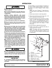
DEALER SET-UP INSTRUCTIONS
Assembly of this equipment is the responsibility of the
Woods dealer. It should be delivered to the owner
completely assembled, lubricated, and adjusted for
normal operating conditions.
Assembly will be easier if components are aligned
and loosely assembled before tightening hardware.
Recommended torque values for hardware are
located on page 47.
ASSEMBLY TABLE OF CONTENTS
MAIN ASSEMBLY. . . . . . . . . . . . . . . . . . . . . . . . . . . . . . . . . . . . . . . . . . . . . . . . . . . . . . . . . . . . . 15
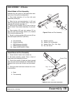
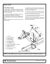
MANUAL CONFIGURATION
OFFSET LINKAGE - MODELS: M & MT. . . . . . . . . . . . . . . . . . . . . . . . . . . . . . . . . . . . . . . . . . . . 18
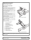
HYDRAULIC ANGLE KIT - MODELS: MA, SA, TA, AND OPTIONAL KIT 1004870 . . . . . . . . . . 19
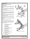
HYDRAULIC TILT KIT - MODELS: MT & TA . . . . . . . . . . . . . . . . . . . . . . . . . . . . . . . . . . . . . . . . 20
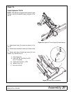
HYDRAULIC OFFSET KIT - MODEL: SA AND OPTIONAL KIT 1004872 . . . . . . . . . . . . . . . . . . 22
HYDRAULIC CONFIGURATION
MODEL H . . . . . . . . . . . . . . . . . . . . . . . . . . . . . . . . . . . . . . . . . . . . . . . . . . . . . . . . . . . . . . . . . . . 23
SELECTOR VALVE KIT 1004873 (OPTIONAL) . . . . . . . . . . . . . . . . . . . . . . . . . . . . . . . . . . . . . . 25
OPTIONAL EQUIPMENT - ALL MODELS
PNEUMATIC TAIL WHEEL (OPTIONAL) . . . . . . . . . . . . . . . . . . . . . . . . . . . . . . . . . . . . . . . . . . . 27
SKID SHOE KIT 18296 (OPTIONAL) . . . . . . . . . . . . . . . . . . . . . . . . . . . . . . . . . . . . . . . . . . . . . . 28
END PLATE KIT 22658 (OPTIONAL) . . . . . . . . . . . . . . . . . . . . . . . . . . . . . . . . . . . . . . . . . . . . . . 29
PRE-DELIVERY & DELIVERY CHECK LISTS . . . . . . . . . . . . . . . . . . . . . . . . . . . . . . . . . . . . . . . 29
CAUTION