


10 Operation
MAN0160 (Rev. 2/22/2006)
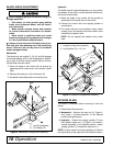
BLADE ANGLE ADJUSTMENT
Before changing positions of manual swing, tilt,
or angle positions:
• Park tractor on level ground, apply parking
brake, level implement boom, shut off tractor,
and remove key.
• Make manual changes slowly and carefully
to prevent hazardous movement of mecha-
nisms.
• Never stand in positions where you could
become entrapped during adjustment changes
or if the 3-point hitch suddenly lowers.
Always secure lock pins with safety pins to pre-
vent lock pins from bumping out of the positioning
holes. Failure to do so may result in accidents
and/or damage to blade.
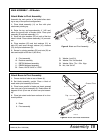
Mechanical
The blade may be angled 15, 30, 45 and 60 degrees
for forward grading, and 15 and 30 degrees for backfill-
ing to right or left from center position without unhook-
ing the blade from the tractor.
1. Raise the blade a few inches off the ground by
operating the lift control lever of the tractor 3-point
hitch.
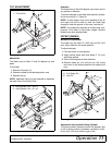
2. Remove the safety pin (10) and lock pin (2).
3. Set blade at desired position and replace pins.
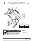
Figure 2. Mechanical Configuration Assembly
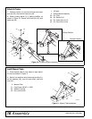
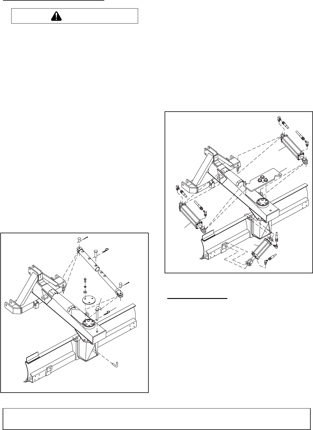
Hydraulic
The blade may be angled 45 degrees or to any position
in between, to the right or left by hydraulic remote con-
trol from the tractor seat.
1. Raise the blade a few inches off the ground by
operating the lift control lever of the tractor.
2. Actuate the control valve the angling cylinder is
connected to.
3. On tractors with two circuit selector valves, select
angling circuit and actuate the tractor control valve
connected to selector valve.
NOTE: Do not operate the selector valve under
load.
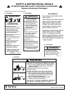
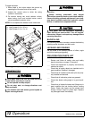
Figure 3. Hydraulic Configuration Assembly
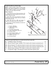
REVERSE BLADE
The blade is reversible without removing it from the
tractor.
1. Raise blade off the ground.
2. Mechanical – Remove the lock pin (2), Figure 2,
and rotate it counter-clockwise to the desired
position and replace pins.
3. Hydraulic – Detach the angling cylinder (7) from
the hydraulic angle arm (1), Figure 3, and rotate it
counter-clockwise to the desired position. Attach
angling cylinder (7) to hydraulic angle arm (1).
NOTE: In some cases it may be necessary to offset to
the right and tip up the right end of the blade to rotate it.
CAUTION
CD5980-1
10
2
2. Lock Pin Assembly
10. 3/16 Safety Pin
1
CD5999-1
Angle
Tilt
Swing
5
5
4
1. Hydraulic Angle Arm Assembly
5. Hyd Cylinder 3.5 x 1.5 x 16