


Assembly 27
MAN0160 (Rev. 2/22/2006)
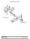
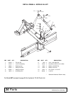
OPTIONAL EQUIPMENT - ALL MODELS
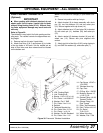
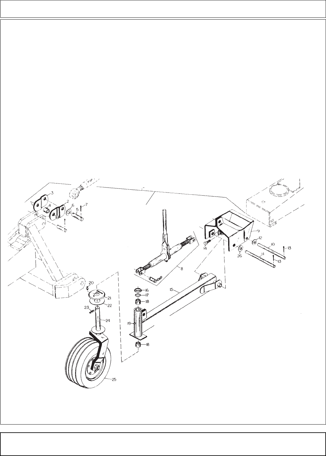
Install Pneumatic Tailwheel 28775
(Optional)
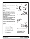
IMPORTANT
■ When grading with tailwheel attached, do not
attach upper link of tractor 3-point hitch to blade
without using floating links (2 & 3). Without float-
ing links, equipment damage may result and void
warranty.
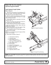
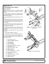
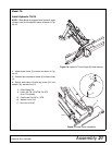
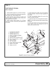
Refer to Figure 30.
The tailwheel is very helpful for finish grading and lev-
eling work. The ratchet controls the approximate cut-
ting height.
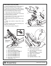
1. Remove top link of tractor 3-point hitch.
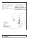
2. Attach float links (2 & 3) and sleeve (4) to inside
of the top holes of A-Frame. 3/4 dia. welded pin on
side of float links must face outward and be located
on the bottom end.
NOTE: Do not use with Category 2 quick-attach cou-
plers.
3. Secure into position with top link pin.
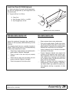
4. Attach bracket (9) to boom assembly with clevis
pin (10), two flat washers (12) and two cotter pins
(13). Secure together with cap screw (14).
5. Attach tailwheel arm (15) and yoke (24) to bracket
(9) with clevis pin (11), washers (26), and cotter pin
(13).
6. Attach ratchet (8) between bracket (9) and tail-
wheel arm (15). Secure with pins supplied with
ratchet.
7. Attach top link to float links (2 & 3) using clevis pin
(5), two SAE flat washers (6), and cotter pins (7).
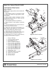
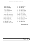
1
2. Link, Floating Right
3. Link, Floating Left
4. Sleeve, 1.00 x 1.25 x 1.44
5. Pin, Clevis 1 x 4-29/32 HT
6. Washer, Flat 1” SAE
7. Pin, Cotter 1/4 x 2-1/4
8. Ratchet
9. Tailwheel Bracket Asy
10. Pin, Clevis 3/4 x 12-1/4
11. Pin, Clevis 1 x 12-1/4
12. Washer, Flat 3/4 Standard
13. Pin, Cotter 1/4 x 1-1/2
14. Cap Screw, 1/2 NC x
1-3/4 GR5
15. Tailwheel Arm Asy
16. Cap, Dust
17. O-Ring .09 x 1.56 OD
18. Bushing, Bronze 1.5
x 1.63 x 1.50
19. Grease Fitting, 1/4-28
Tapered Thread
20. Grease Fitting, 1/8
Pipe Thread
21. Plate, Top Dampener
22. Disc, Friction 4 x 6.15
23. Pin, Spirol
7/16 x 2-1/2
24. Wheel Yoke Asy
26. Washer, Flat 1” Std
Fi
g
ure 30. Pneumatic Tailwheel Installation