Operation 15
15914 (Rev. 3/23/2007)
7. Repeat step 6 for the other half of the drive.
8. File and clean cut ends of both drive halves.
Do not use tractor if proper driveline engagement can-
not be obtained through these methods.
Connect driveline to tractor PTO shaft, making sure the
spring-activated locking collar slides freely and locks
driveline to PTO shaft.
NOTICE
■ If attaching with quick hitch the distance
between the tractor PTO and gearbox input shaft
will increase. Please follow the steps as you would
for a 3-point hitch to insure proper engagement.
Cutting Height Adjustment for MD80
Mounted Cutter
Place tractor and cutter on a level surface.
The adjustments given here are to provide you with a
starting point. Adjustments are approximate and may
vary due to slight differences in blade shimming and
machine wear. You may desire to fine tune them for
your situation.
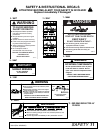
Keep all persons away from operator control
area while performing adjustments, service, or
maintenance.
■ Avoid very low cutting heights. Striking the
ground with blades produces one of the most dam-
aging shock loads a cutter can encounter. Allowing
blades to contact ground repeatedly, will cause
damage to cutter and drive.
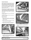
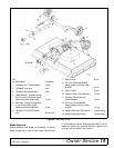
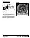
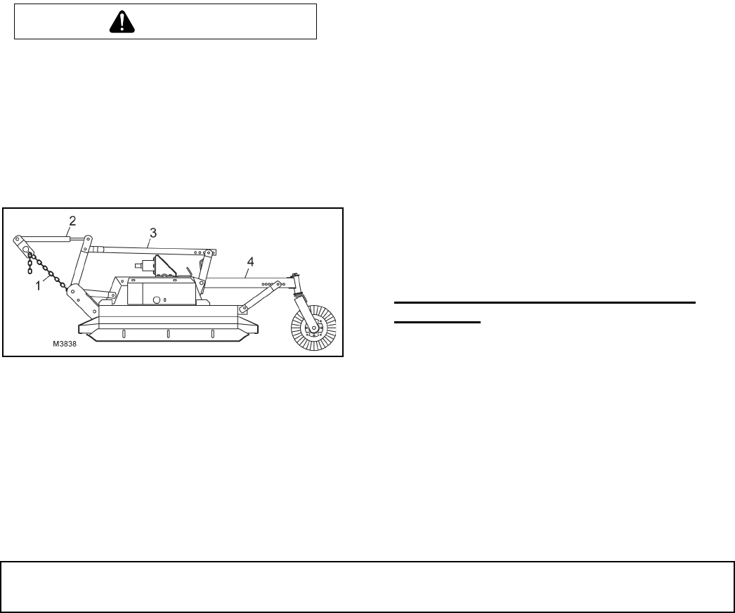
Figure 5. Cutting Height Adjustment - MD80
(Mounted Model)
Cutting height may be controlled by several methods.
Without the optional check chains and tailwheel it is
controlled with the tractor 3-point lift and top link adjust-
ment.
Measure from front edge of cutter frame (on each side)
to ground to be sure cutter is level. Use adjustment on
3-point arms, if necessary, for fine adjustment side to
side.
When using optional check chains, install them in key-
hole brackets. Count the links between the cutter and
brackets to be sure you have the same number of links
on each side. You may twist check chain for fine adjust-
ment side to side.
Cutting Height Adjustment Without
Tailwheel or Check Chains
The blade is approximately 9-1/4" below the top of the
cutter deck.
Select a cutting height, EXAMPLE 3".
Use tractor 3-point lift to set front blade 3" above level
surface (measure 12-1/4" from top of deck to ground).
At the rear, measure from top of deck to ground; adjust
top link until this distance is from 12-3/4" to 13". Adjust
lower stop of the tractor 3-point lift control. When
adjustment is set, this will enable you to return to the
preset cutting height.
Maintain distance from blade tip to level surface from
1/2" to 3/4" higher at rear for best cutting results and
lowest power consumption.
When using cutter for shredding, it is better to set blade
tip lower at the rear. How much lower depends on the
material to be shredded. You will need to experiment to
determine the best setting for your situation.
Cutting Height Adjustment With Tailwheel
or Check Chains
The blade is approximately 9-1/4" below the top of the
cutter deck.
Select a cutting height, EXAMPLE 3".
Use check chains and tractor 3-point lift and raise top
front of cutter deck 12-1/4" above the level surface. At
the rear, measure from top of deck to ground; adjust
tailwheel until this distance is from 12-3/4" to 13".
Shorten the check chains to raise front of cutter. Move
tailwheel adjustment to the rear to raise rear of cutter.
ATTACHING PULL-TYPE CUTTER TO
TRACTOR
The cutter is shipped with a 1-3/8" PTO spline. The
horizontal distance between the end of the tractor PTO
shaft and the drawbar hitch point should be 14". This
distance must not vary more than plus or minus one
inch (±1") or the drive may be damaged when turning.
Adjust tractor drawbar to obtain the desired drawbar to
hitch point distance. On some tractors, a drawbar kit
must be used to obtain the required dimension. Check
with your tractor dealer if you encounter problems.
Raise cutter tongue to tractor drawbar height with jack
provided and attach with a 3/4" or larger high-strength
drawbar pin. Retain pin to keep it in place.
WARNING


