


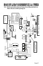
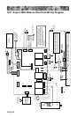
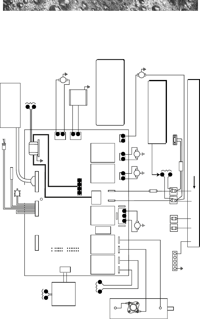
19.0 Export 50Hz Maxxus Electrical Wiring Diagram
SENSORS 800 LCD PANEL
230 VAC, 34A / 42A, 1-Phase, 50 Hz;
USE MIN. 6 AWG (10mm
2
) COPPER CONDUCTORS ONLY
J8 J6 J7
J3
OPTIONS
FLOW SWITCH
HI - LIMIT / FREEZE SENSOR
TRANSFORMER
T1
TB3
TB3 TB4
G
11
11 2
TB2
2 1
1
2
PUMP 1 PUMP 2 PUMP 3
HI
HI
TEMPERATURE
SENSOR
TB7
From TB1
Terminal Block
TB1
TB2
UV or CD
Ozonator
(Optional)
HEATER
5.5 kW, 240 VAC
Circulation
Pump
TB5
TB1
2
1
1
TB6
2
1
1 2 3
HI
30A,
250V
SC-30
F1
For Connection To Two Power Supplies,
Remove These Wires And Connect To
Top Terminals on TB2. Then Connect
2nd Supply To Bottom TB2 Terminals.
BLU (N)
GRN/YEL (GND)
N N N N
N
L N
N
L L L L
L
L
BRN (L)
L
L
N
N
LN
Red
Red
Black
Black
B B Y Y
J4
STEREO
(Optional)
Power Supply
This equipment was tested and found
to be fully compliant with EN55014-1
(1997), EN55014-2 (1997), EN61000-3-2
(1995), EN61000-3-3 (1995), EN55022
Class B, and EN50082-1 (1992)
Standards.
X
W
WaterfallLight/
Footwell Light
Controller
12VAC From
T1 Transformer
X
W
12VAC Output to
Waterfall Light/
Footwell Light
Controller
N
L
Blower
To Heater
Relay
Z
Y
Z
Y
Maxxus
Control Panel
JP20
JP19
JP9
1
1
3
5
7
9
1
3
5
7
9
11
13