


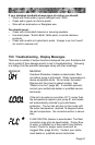
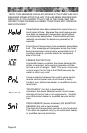
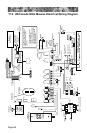
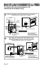
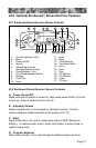
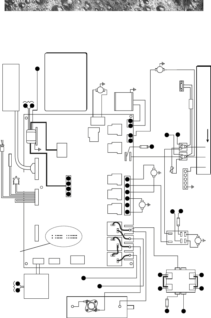
17.0 US/Canada 60Hz Maxxus Electrical Wiring Diagram
SENSORS 800 LCD PANEL
240 VAC, 38A / 48A
1 PHASE, 60 Hz; USE MIN. 6 AWG
COPPER CONDUCTORS ONLY
J4
J8
J2
K8
K14
K6K5K4
K1 K2 K3
K7
J1
Z1
J6 J7
J3
OPTIONS
FLOW SWITCH
HI - LIMIT / FREEZE SENSOR
TRANSFORMER
T1
RED
Red
BLU
GRN/YEL
Wht
Wht
Blk
Blk
Blk
Blk
Red
BRN
BLK
Blk
PUMP 3
PUMP 1
T92 Pump 2
Relay
HI
Wht
Wht
Blk
Blk
Blk
Wht
PUMP 2
HI
HI
TB3
TB2 TB6
TB1
TB1
GRN
1
X
W
B B Y Y
3 5
6
8
10
1 2 1
2
TEMPERATURE
SENSOR
To Pump 2 Relay &
Heater Relay
From TB1
From
Contactor
KX-2
From
TB1
From
Contactor
KX-2
TB5
TB3
K13
TB4
30A,
250V
SC-30
F1
CD
Ozonator
(Optional)
INTERLOCK
JUMPER
HEATER
5.5 kW, 240 VAC
Circulation
Pump
Blower
STEREO
(Optional)
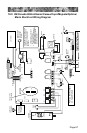
This device complies with part 15
of the FCC rules. Operation is
subject to the following two
conditions:
1. This device may not cause
harmful interference.
2. This device must accept any
interference received including
interference that may cause
undesired operation.
Power Supply
20A, 250V
MDA20
F2
Maxxus
Control Panel
X
W
12VAC Output to
Waterfall Light/
Footwell Light
Controller
Waterfall
Light &
Footwell
Light
Controller
12VAC From
T1 Transformer
P1
H
P1
H
Z
Z
Z
T
T
H
1
2
2A, 250V
FX
From
TB1
KX-3
KX-1
KX-2
KX-4
From
Contactor
KX-3
Contactor
To
Xfmr.
To Contactor KX-1
(2 Wires) & Fuse FX
(1 Wire)
Two Wires From TB1
Z
P1
P2
To 30A
Fuse F1
To Fuse F2 & Heater
Relay (2 Locations)
P2
From Contactor KX-2
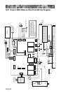
JP20
JP19
JP9
1
1
3
5
7
9
1
3
5
7
9
11
13
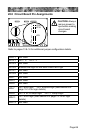
See page 69 for
jumper settings