


DCA-800SSK (STD) — OPERATION AND PARTS MANUAL — REV. #4 (06/03/10) — PAGE 31
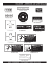
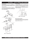
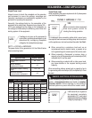
8. Tachometer - Indicates engine speed in RPMs for 60Hz
operation. Normal operation is 1800 RPMs when the load
is applied. A built in hour meter will record the number of
operational hours that the generator has been in use.
8. Oil Pressure gauge - This gauge indicates the oil
pressure. During normal operation, the gauge should read
in the 'green' zone. When starting the generator, the oil
pressure may read slightly higher, but after the engine
warms up, it should return to the "
green
" zone.
9. Water Temp Gauge - This indicates the temperature of the
coolant. During normal operation this gauge should read
in the 'green' zone.
11. Charging Ammeter Gauge - This gauge indicates the
current supplied by the alternator, which supplies current
from the generator's control circuits and battery charging
system.
12. Fuel Level Gauge - This gauge indicates diesel fuel level.
13. Engine Speed Switch
(S/N 3699248~) – This switch
changes the engine speed from
low
(idle) to
high
.
14. Preheat Button – Press and hold this button for
30seconds until the preheat lamp is lit (ON).
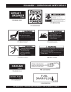
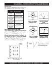
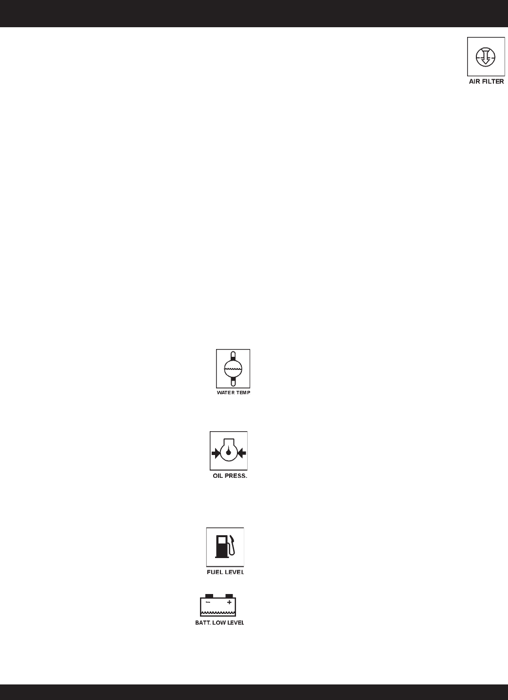
E. Clogged Air Filter Lamp - This indicates
the air filter is clogged. Stop the engine
and replace the air filter.
C. Low Fuel Level Lamp - When lit, this
indicates to add fuel. Let the engine cool
before adding diesel fuel.
D. Low Battery Fluid Lamp - This indicates
the battery fluid level is low. This
indicator will shut down the engine. Refill
the battery with distilled water.
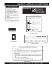
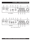
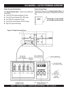
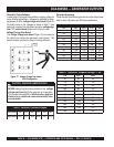
The definitions below describe the controls and functions of the
DCA-800SSK "
Engine Operating Panels
" (Figure 11).
1. Air Cleaner Indicators – When lit, indicates air cleaner
must be serviced or replaced. This engine of this generator
requires two air cleaners.
2. Battery Switch – This switch should be set to the "ON"
position during normal operation. When the engine has
been stopped, place this switch in the "OFF" position. DO
NOT turn this switch during normal operation; it will cause
damage to the electrical equipment.
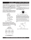
3. Ignition Switch (Up to S/N 3699247) – Four position
switch,
pre-heat
,
stop
,
run
and
start
. Insert ignition
key to start and stop engine.
.
4. Preheat Lamp – Indicates that the glow plugs of the
diesel engine are hot is ready to start.
5. Emergency Stop Button – Press this button to stop the
engine in the event of an emergency. DO NOT use this
button as a normal means of stopping the engine.
6. Oil Filter Alarm Lamp – Indicates the oil filter is clogged
and needs replacement.
7. Engine Warning Display (LED) Module – This module
display’s the following engine failures:
B. Low Oil Pressure Lamp - This lamp will
turn on if the Auto-OFF/Reset-Manual
switch on the Engine Controller is set in
"Manual" position. It will remain lit until the
oil pressure is at a normal level. If the lamp
turns on at any time during the normal
working time of the generator, it will shut
down the engine.
A. Overheat Lamp - This lamp turns on when
the cooling water temperature rises beyond
normal level. If the this light is on, the
emergency shutdown device will stop the
engine.
DCA-800SSK — ENGINE OPERATING PANEL