


Installation & Operation Manual
8 Maintenance (continued)
59
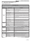
Check relief valve
1. Inspect the relief valve and lift the lever to verify flow. Before
operating any relief valve, ensure that it is piped with its
discharge in a safe area to avoid severe scald potential. Read
Section 4 - Water Connections of the Copper-fin
2
Installation
and Operation Manual before proceeding further.
Safety relief valves should be re-inspected
AT LEAST ONCE EVERY THREE YEARS,
by a licensed plumbing contractor or
authorized inspection agency, to ensure
that the product has not been affected by
corrosive water conditions and to ensure
that the valve and discharge line have not
been altered or tampered with illegally.
Certain naturally occurring conditions may
corrode the valve or its components over
time, rendering the valve inoperative. Such
conditions are not detectable unless the
valve and its components are physically
removed and inspected. This inspection
must only be conducted by a plumbing
contractor or authorized inspection agency
– not by the owner. Failure to re-inspect
the pool heater relief valve as directed could
result in unsafe pressure buildup, which can
result in severe personal injury, death, or
substantial property damage.
Following installation, the valve lever must
be operated AT LEAST ONCE A YEAR to
ensure that waterways are clear. Certain
naturally occurring mineral deposits may
adhere to the valve, rendering it inoperative.
When manually operating the lever, water
will discharge and precautions must be taken
to avoid contact with hot water and to avoid
water damage. Before operating lever, check
to see that a discharge line is connected to
this valve directing the flow of hot water
from the valve to a proper place of disposal.
Otherwise severe personal injury may result.
If no water flows, valve is inoperative. Shut
down the appliance until a new relief valve
has been installed.
2. After following the above warning directions, if the relief
valve weeps or will not seat properly, replace the relief valve.
Ensure that the reason for relief valve weeping is the valve
and not over-pressurization of the system due to expansion
tank waterlogging or undersizing.
ƽ WARNING
ƽ WARNING
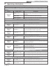
Inspect/replace hot surface igniter
This unit uses a proven SMART SYSTEM control module and
a hot surface igniter. The SMART SYSTEM control module is
not repairable. Any modification or repairs will invalidate the
warranty.
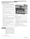
Check all wiring
1. Inspect all wiring, making sure wires are in good condition
and securely attached.
Check control settings
1. Set the SMART SYSTEM control module display to
Parameter Mode and check all settings. Reference the
Copper-fin
2
Service Manual for how to adjust settings and
parameters. Adjust settings if necessary.
2. Check settings of external limit controls (if any) and adjust
if necessary.
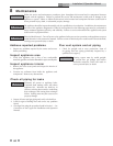
Do not attempt to repair a faulty hot surface
igniter or control module. Any modification
or repairs may create hazardous conditions
that result in property damage, personal
injury, fire, explosion and/or toxic gases.
ƽ WARNING
A faulty hot surface igniter or control module must be replaced
with an identical part. A specification igniter and control
module for this specific unit is available from your local
distributor. Do not use general purpose field replacement
control modules or igniters.
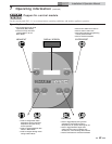
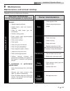
Ignition system checkout
1. Turn off gas supply to unit.
2. Turn electric power on.
3. Adjust the set point on the temperature control to a
setting above water temperature or to the highest safe
setting.
4. The igniter will cycle on trial for ignition.
5. The control module will lock out and turn the alarm
light on.
6. Adjust the Set Point Differential and High-Fire Offset to
the desired settings.
7. Turn on gas supply.
8. Press the RESET button at the electronic display panel to
reset the control module.
9. If ignition system fails to operate properly, repair work
must be performed by a qualified service person or
installer.