


Installation & Operation Manual
16
2 Venting
A
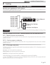
Conventional negative draft venting - see page 14.
NOTICE
Before installing a venting system, follow requirements found in the General Venting section.
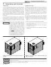
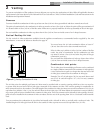
This option uses Type-B double-wall flue outlet piping. The blower brings in combustion air. The buoyancy of the
heated flue products cause them to rise up through the flue pipe. The flue outlet terminates at the rooftop.
Negative draft
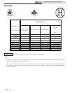
The negative draft in a conventional vent installation must be within the range of 0.02 to 0.08 inches w.c. to ensure
proper operation. Make all draft readings while the unit is in stable operation (approximately 2 to 5 minutes).
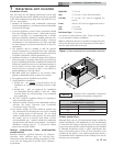
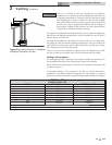
Connect the flue vent directly to the flue outlet opening on the top of the unit. No additional draft diverter or
barometric damper is needed on single unit installations with a dedicated stack and a negative draft within the
specified range of 0.02 to 0.08 inches w.c. If the draft in a dedicated stack for a single unit installation exceeds the
maximum specified draft, you must install a barometric damper to control draft. Multiple unit installations with
combined venting or common venting with other Category I negative draft appliances require each pool heater to
have a barometric damper installed to regulate draft within the proper range.
Do not connect vent connectors serving appliances vented by natural draft (negative draft) to any portion of a
mechanical draft system operating under positive pressure. Connecting to a positive pressure stack may cause flue
products to be discharged into the living space causing serious health injury.
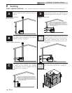
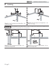
Flue outlet piping
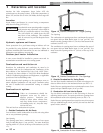
With this venting option, you must use Type-B double-wall vent materials. Vent materials must be listed by a
nationally-recognized test agency for use as vent materials. Make the connections from the unit vent to the outside
stack as direct as possible with no reduction in diameter. Use the National Fuel Gas Code venting tables for double-
wall vent to properly size all vent connectors and stacks. Follow the vent manufacturer’s instructions when installing
Type-B vents and accessories, such as firestop spacers, vent connectors, thimbles, caps, etc.
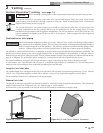
Provide adequate clearance to combustibles for the vent connector and firestop.
When planning the venting system, avoid possible contact with plumbing or electrical wiring inside walls, ceilings,
and floors. Locate the unit as close as possible to a chimney or gas vent.
Avoid long horizontal runs of the vent pipe, 90° elbows, reductions and restrictions.
No additional draft diverter or barometric damper is required on single unit installations with a dedicated stack and
a negative draft maintained between 0.02 to 0.08 inches w.c.
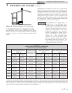
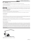
Common Venting Systems
You can combine the flue with the vent from any other negative draft, Category I appliance. Using common venting
for multiple negative draft appliances requires you to install a barometric damper with each unit. This will regulate
draft within the proper range. You must size the common vent and connectors from multiple units per the venting
tables for Type-B double-wall vents in the latest edition of the National Fuel Gas Code, ANSI Z223.1 and/or CAN/
CGA-B149 Installation Code.
Common venting systems may be too large when an existing unit is removed.
At the time of removal of an existing appliance, the following steps shall be followed with each appliance remaining
connected to the common venting system placed in operation, while other appliances remaining connected to the
common venting system are not in operation.
1. Seal any unused opening in the common venting system.
2. Visually inspect the venting system for proper size and horizontal pitch. Make sure there is no blockage or
restriction, leakage, corrosion and other unsafe conditions.
3. If possible, close all building doors and windows. Close all doors between the space in which the appliances
remaining connected to the common venting system are located and other building spaces.