


32
3 Gas connections
Installation & Operation Manual
2. Use new, properly threaded black iron pipe free from
chips. If you use tubing, make sure the ends are cut
square, deburred and clean. Make all tubing bends smooth
and without deformation. Avoid flexible gas connections.
Internal diameter of flexible lines may not provide unit with
proper volume of gas.
3. Install a manual main gas shutoff valve at the unit’s gas inlet,
outside of the unit.
4. Run pipe or tubing to the unit’s gas inlet. If you use tubing,
obtain a tube to pipe coupling to connect the tubing to the
unit’s gas inlet.
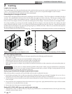
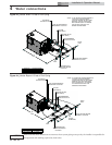
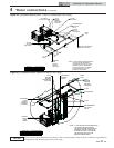
5. Install a sediment trap in the supply line to the unit’s gas
inlet (see FIG. 3-1).
6. Apply a moderate amount of good quality pipe compound
(do not use Teflon tape) to pipe only, leaving two end
threads bare.
7. Remove seal over gas inlet to unit.
8. Connect gas pipe to inlet of unit. Use wrench to support gas
manifold on the unit.
9. For L.P. gas, consult your L.P. gas supplier for expert
installation.
10. Ensure that all air is completely bled from the gas line before
starting the ignition sequence. Start up without properly
bleeding air from the gas line may require multiple reset
functions of the ignition control module to achieve proper
ignition.
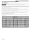
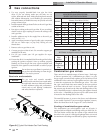
TABLE - 3C
FITTINGS TO EQUIVALENT STRAIGHT PIPE
Diameter
Pipe
(inches)
3/4 1 1 1/4 1 1/2 2 3 4 5
Equivalent
length of
Straight Pipe
(feet)
22345101420
ƽ WARNING
Do not have any open flame in proximity to
the gas line when bleeding air from the gas
line. Gas may be present.
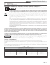
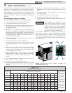
TABLE 3B
SUGGESTED GAS PIPE SIZE FOR
SINGLE UNIT INSTALLATIONS
MODEL
Distance from Meter (in feet)
0 - 50 51 - 100 101 - 200 201 - 300 301 - 500
502 1 1/4" 1 1/2" 2" 2" 2 1/2"
652 1 1/2" 2" 2" 2 1/2" 2 1/2"
752 1 1/2" 2" 2" 2 1/2" 3"
992 2" 2" 2 1/2" 2 1/2" 3"
1262 2" 2 1/2" 2 1/2" 3" 3"
1442 2 1/2" 2 1/2" 3" 3" 3 1/2"
1802 2 1/2" 3" 3" 3 1/2" 3 1/2"
2072 2 1/2" 3" 3" 3 1/2" 4"
For each elbow or tee, add equivalent straight pipe to total length from Table 3C.
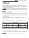
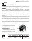
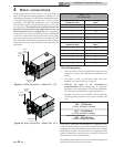
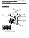
Gas train and controls
NOTICE
The gas train and controls assembly
provided on this unit have been tested under
the applicable American National Standard
to meet minimum safety and performance
criteria such as safe lighting, combustion
and safety shutdown operation.
COMBINATION
VALVE
DOWNSTREAM
TEST VALVE
TO BURNERS
502 MODEL
COMBINATION
VALVE
DOWNSTREAM
TEST VALVE
TO BURNERS
2072 MODEL
Figure 3-2_Typical Pool Heater Gas Train Drawing
Combination gas valves
These units fire in multiple stages of burner input. Each stage
of burner operation has a combination gas valve(s) to cycle
the gas supply on and off and regulate gas to the burners. Each
combination valve consists of a gas regulator and two valve seats
to meet the requirements for redundant gas valves. The valve
has a gas control knob that must remain in the open position
at all times when the unit is in service. The gas control valve
has pressure taps located on the inlet and discharge sides of the
valve. Manifold pressure is adjusted using the regulator located
on the valve. A manifold gas pressure tap for each burner stick
is located on the discharge side of the valve.
The manifold pressure is preset at the factory and adjustment
is not usually required. If you must adjust regulator pressure,
follow the instructions in the Copper-fin
2
Service Manual.
Venting of combination gas valves
The combination gas valve/regulator used on all units is
equipped with an integral vent limiting orifice per ANSI Z21.78.
The vent limiter ensures that the volume of gas emitted from
the valve in the event of a failed gas diaphragm does not exceed
the maximum safe leakage rate allowed by agency requirements.