


24
2 Venting
Installation & Operation Manual
ƽ WARNING
Do not combine the flue from this unit with the vent from any other appliance. Do not combine flues from
multiple appliances into a common vent. The flue from this unit must be a dedicated stack.
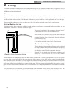
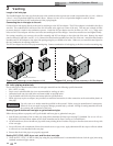
Connect the flue vent directly to the flue outlet opening on the top of the unit. Make the connections from the unit vent to the
outside stack as direct as possible with no reduction in diameter. Provide adequate clearance to combustibles for the vent connector
and firestop. Follow the vent manufacturer’s instructions when installing sealed AL29-4C vents and accessories, such as firestop
spacers, vent connectors, thimbles, caps, etc.
Provide adequate clearance to combustibles for the vent connector and firestop.
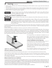
When planning the venting system, avoid possible contact with plumbing or electrical wiring inside walls, ceilings, and floors.
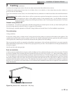
Locate the unit as close as possible to chimney or gas vent. When a vent system is disconnected for any reason, the flue must be
reassembled and resealed according to the vent manufacturer’s instructions.
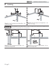
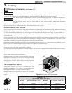
The installed length of flue from the unit to the outside point of termination must not exceed 50 equivalent feet (15.2 m). Subtract
5 feet (1.5 m) of equivalent length for each 90° elbow. Subtract 2.5 feet (0.7 m) of equivalent length for each 45° elbow.
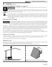
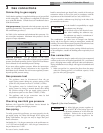
Sidewall vent termination clearances and location
Follow all sidewall venting termination information for clearances and location under Sidewall Vent Termination Clearances and
Location on page 22.
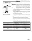
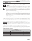
TABLE - 2C
SIDEWALL VENT KITS
MODEL
KIT
(W/POWER FAN ASSY.)
MAX. VENT
LENGTH
VENT TERMINATION
ONLY
(MODELS 502 - 752)
MAX. VENT
LENGTH
502 SVK3006 100 ft. SVK3043 50 ft.
652 SVK3008 100 ft. SVK3044 50 ft.
752 SVK3008 100 ft. SVK3044 50 ft.
992 SVK3009* 100 ft. N/A N/A
1262 SVK3010* 100 ft. N/A N/A
1442 SVK3010* 100 ft. N/A N/A
1802 SVK3012* 100 ft. N/A N/A
2072 SVK3012* 100 ft. N/A N/A
*These kits include a barometric damper.