


31
3 Gas connections
Connecting to gas supply
Verify that the appliance is supplied with the type of gas specified
on the rating plate. This appliance is configured for operation
up to 4,500 feet altitude. Consult factory for installations above
4,500 feet elevation.
Inlet gas pressure: Measured at the inlet pressure tap on the
appliance gas manifold. The pressure tap is located upstream of
the combination gas valve(s).
See Table 3A for maximum and minimum inlet pressures. Do
not exceed the maximum. Minimum inlet pressure is for the
purpose of input adjustment.
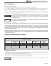
TABLE 3A
INLET GAS PRESSURE
MODEL
NATURAL LP
Max.
w.c.
Min.
w.c.
Max.
w.c.
Min.
w.c.
502 - 2072 14" 4.5" 14" 8.0"
Gas pressure test
1. The appliance must be disconnected from the gas
supply piping system during any pressure testing of that
system at a test pressure in excess of 1/2 PSIG (3.5 kPa).
2. The appliance must be isolated from the gas supply
piping system by closing a manual shutoff valve during
any pressure testing of the gas supply piping system at
test pressures equal to or less than 1/2 PSIG (3.5 kPa).
3. The appliance and its gas connection must be leak
tested before placing it in operation.
Checking manifold gas pressure
Reference the Copper-fin
2
Pool Heater Service Manual for
information regarding manifold gas pressure.
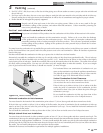
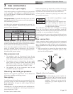
Install a manual main gas shutoff valve, outside of the unit gas
connection within six feet of the unit in accordance with the
requirements of the National Fuel Gas Code, ANSI Z223.1.
You must provide a sediment trap (drip leg) in the inlet of the
gas connection to the unit.
Manifold pressure: The gas regulator on the unit’s
combination gas valve is adjustable to supply proper manifold
pressure for normal operation. See the Copper-Fin
2
Pool Heater
Service Manual for net manifold pressure settings.
If you must adjust regulator pressure, follow the instructions
under Gas Manifold Pressure Adjustment in the Copper-Fin
2
Pool Heater Service Manual. Do not increase regulator pressure
beyond specified pressure setting.
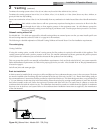
Gas connection
All gas connections must be made with pipe joint compound
resistant to the action of liquefied petroleum (L.P.) and natural
gases. All piping must comply with local codes and ordinances.
Piping installations must comply with approved standards and
practices.
1. Make sure gas line is a separate line direct from the meter
unless the existing gas line is of sufficient capacity. Verify
pipe size with your gas supplier.
NOTICE
It is the installer’s responsibility to supply
the sediment trap (drip leg).
CAUTION
Do not block access to the electrical cover
plate when installing the sediment trap.
The sediment trap must be a minimum of
12 inches from the appliance.
The combination gas valves have an integral vent limiting
device and do not require venting to atmosphere, outside the
building. The unit will not operate properly if the reference hose
is removed or a vent to atmosphere is installed.
Optional gas controls may require routing of bleeds and vents
to the atmosphere, outside the building when required by local
codes.
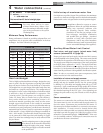
USE WRENCH
TO HOLD
SUPPLY PIPE
12”
MIN
UNION
MANUAL MAIN
SHUTOFF VALVE
NIPPLE
CAP
Figure 3-1_Gas Line Connection
Installation & Operation Manual
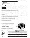
Gas piping
To safely operate this pool heater, you must properly size the
gas supply piping. See Tables 3B through 3D for piping and
fitting requirements. Gas pipe size may be larger than pool
heater connection.
On Models 502 - 752, the gas connection to the pool heaters are
1 1/4" NPT and on Models 992 - 2072, the gas connections to
the pool heaters are 2" NPT.
For ease of service, install a union.
NOTICE
If an inline high gas pressure regulator is
used, it MUST BE of the lockup type and
be located a minimum of 10 feet from the
appliance. Failure to do so may result in
insufficient gas volume supplied to the
appliance.