


2 Venting
30
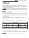
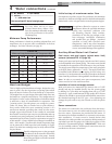
TABLE - 2F
OUTDOOR VENT CAP KITS
MODEL OUTDOOR VENT KIT MODEL OUTDOOR VENT KIT
502 ODK3075 1262 ODK3078
652 ODK3076 1442 ODK3079
752 ODK3076 1802 ODK30005
992 ODK3077 2072 ODK30005
Installation & Operation Manual
Outdoor installation - see page 14.
NOTICE
Before installing a venting system, follow all requirements found in the General Venting section.
Units are self-venting and can be used outdoors when installed with the optional outdoor cap. This cap mounts directly to the top
of the unit and covers the flue outlet and combustion air inlet openings. No additional vent piping is required.
ƽ WARNING
Only install outdoor models outdoors and only use the vent cap supplied by the appliance manufacturer.
Personal injury or product damage may result if any other cap is used or if an outdoor model is used indoors.
Properly install all covers, doors and jacket panels to ensure proper operation and prevent a hazardous
condition.
Combustion air supply must be free of contaminants (see Combustion and Ventilation Air, page 10). To prevent recirculation of
the flue products into the combustion air inlet, follow all instructions in this section.
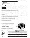
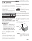
Outdoor vent/air inlet location
Keep venting areas free of obstructions. Keep area clean and free of combustible and flammable materials. Maintain a minimum
clearance of 3" (76 mm) to combustible surfaces and a minimum of 36" (915 mm) clearance to the air inlet. To avoid a blocked
air inlet or blocked flue condition, keep the outdoor cap air inlet, flue outlet and drain slot clear of snow, ice, leaves, debris, etc.
Do not install outdoor models directly on the ground. You must install the outdoor unit on a concrete, brick, block, or other non-
combustible pad.
Do not locate unit so that high winds can deflect off of adjacent walls, buildings or shrubbery causing recirculation. Recirculation
of flue products may cause operational problems, bad combustion or damage to controls. Locate unit at least 3 feet (0.91 m) from
any wall or vertical surface to prevent wind conditions from affecting performance.
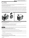
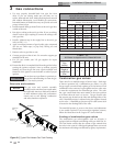
Multiple unit outdoor installations require 48" (1.22 m) clearance between each vent cap. Locate outdoor cap at least 48" (1.22m)
below and 48" (1.22 m) horizontally from any window, door, walkway or gravity air intake.
Locate unit at least 10 feet (3.05 m) away from any forced air inlet.
Locate unit at least 3 feet (0.91 m) outside any overhang.
Clearances around outdoor installations can change with time. Do not allow the growth of trees, shrubs or other plants to obstruct
the proper operation of the outdoor vent system.
Do not install in locations where rain from building runoff drains will spill onto the unit.
Do not install outdoor units on stack frames.
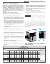
Flue gas condensate can freeze on exterior walls or on the vent
cap. Frozen condensate on the vent cap can result in a blocked
flue condition. Some discoloration to exterior building or unit
surfaces can be expected. Adjacent brick or masonry surfaces
should be protected with a rust resistant sheet metal plate.
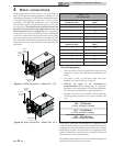
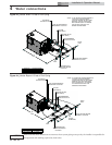
The outdoor vent cap kit
The optional outdoor vent cap kit is available from the
appliance manufacturer. The outdoor cap part numbers are
listed by model number. See Table 2F for kit numbers.
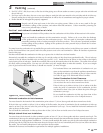
Install the outdoor vent cap on the rear of the unit. Complete
installation instructions are included with the outdoor vent
cap kit.
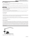
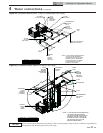
Figure 2-14_Outdoor Vent Cap Installed
3'
MIN
3'
MIN
3'
MIN
3'
MIN
F