


2 Venting (continued)
27
Installation & Operation Manual
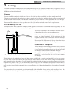
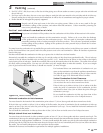
Masonry chimney installation
Do not use a standard masonry chimney to directly vent the combustion products from this unit.
To use a masonry chimney, the chimney must use a sealed, corrosion-resistant liner system. Sealed, corrosion-resistant liner
systems (single-wall, double-wall, flexible, or rigid) must be rated for use with a high efficiency, positive pressure vent system.
Corrosion-resistant chimney liner systems are typically made from a high grade stainless steel such as AL29-4C. The liner must be
properly sized and fully sealed throughout the entire length. Both the top and bottom of the masonry chimney must be capped
and sealed to provide a dead air space around the liner.
ƽ WARNING
Do not vent this unit into a masonry chimney without a sealed stainless steel liner system. Any breaks, leaks,
or damage to the masonry flue/tile will allow the positive-pressure flue products to leak from the chimney and
into occupied living spaces. This could cause serious injury or death due to carbon monoxide poisoning and
other harmful flue products.
NOTICE
Check with local code officials to determine code requirements or the advisability of using a masonry chimney
with a sealed corrosion-resistant liner system.
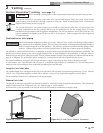
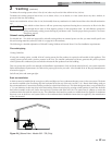
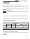
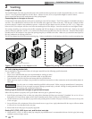
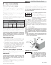
Horizontal DV venting termination
Horizontal venting uses the unit’s internal combustion air blower to force the flue products out of the horizontally-terminated flue.
You must purchase a horizontal direct vent kit from the appliance manufacturer to ensure proper operation. When installing
the vent cap, the wall opening must provide an air space clearance of 2 inches (5.1 cm) around the flue pipe. The diameter of the
opening for installation of the sidewall cap will be 4 inches (10.2 cm) larger (minimum) than the nominal diameter of the installed
vent pipe to the horizontal vent cap.
Install the horizontal vent cap from the outside. Mount the vent cap to the wall using four screws or wall anchors. Seal under the
screw heads with caulking. Install the Category IV vent pipe from the unit to the vent cap. See detailed instructions packed with
the horizontal direct vent kit.
Horizontal Vent Termination Clearances and Location
Follow all sidewall venting termination information for clearances and location under Sidewall Vent Termination Clearances and
Location, page 22.
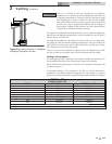
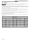
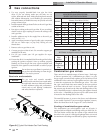
TABLE - 2E
DIRECT VENT KITS
MODEL
HORIZONTAL
KIT*
VERTICAL
KIT*
MODEL
HORIZONTAL
KIT*
VERTICAL
KIT*
502 DVK3004 VDK3026 1262 DVK3001 VDK3024
652 DVK3005 VDK3027 1442 DVK3001 VDK3024
752 DVK3005 VDK3027 1802 DVK30000 VDK3024
992 DVK3000 VDK3023 2072 DVK30000 VDK3024
*These kits include a DV box adapter, air inlet cap, and a sidewall vent termination. The VDK kits include a DV box adapter and an air inlet cap.
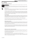
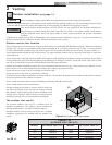
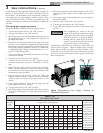
Combustion air inlet piping
The Direct Vent system requires the installation of a pipe to supply combustion air from the outdoors directly to the unit. Make
sure the combustion air inlet is in the same pressure zone as the vent terminal.
In cold climates, use a Type-B double-wall vent pipe or an insulated single wall pipe for combustion air. This will help prevent
moisture in the cool incoming air from condensing and leaking from the inlet pipe.
ƽ CAUTION
Units that are shut down or will not operate may experience freezing due to convective airflow in the air inlet
pipe.