


5
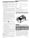
The Copper-fin
2
- How it works...
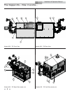
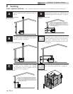
1. Heat exchanger
The heat exchanger allows system water to flow through specially
designed tubes for maximum heat transfer. The glass lined
headers and copper fined tubing are encased in a jacket that
contains the combustion process.
2. Heat exchanger access cover
The heat exchanger access cover is a galvanized steel door which
allows access for service, maintenance, and removal of the
heat exchanger from inside the combustion chamber.
3. Blower
The blower pulls in and injects air into the individual burners
along with gas from the gas manifold where the mix is burned inside
the combustion chamber.
4. Gas valve
The referenced gas valves have a dual purpose; changing the gas
supply pressure to manifold pressure, and the reference side of
the gas valve is designed to allow chamber pressure to change the
volume of gas through the valve. This is not a design to
compensate for gas supply pressure issues.
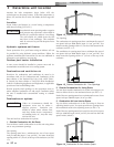
5. Outlet/limit temperature sensor
This 4-wire limit rated sensor monitors the outlet temperature
to ensure safe operation. The appliance will adjust its firing rate
to maintain water temperatures below the maximum allowable
outlet temperature.
6. Inlet temperature sensor
This 2-wire sensor monitors the inlet temperature. The appliance
will adjust the position of the 3-way valve to maintain the inlet
water temperature above the minimum allowable inlet
temperature.
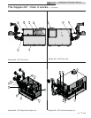
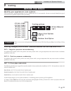
7. Electronic display
The electronic display consists of 6 buttons and a two-line
16-character liquid crystal display used to monitor the
operation of the heater as well as enter and view the
programming of the main control board.
8. Burner
The burner is a ported stainless steel construction which uses a gas
air mix to operate at a fixed input. Banks of burners turn on
or off to vary the firing rate.
9. Pool supply/limit sensor (not shown)
This 4-wire limit rated sensor monitors the temperature of
the water being supplied to the pool to ensure safe operation.
The appliance will shut down if the maximum allowable pool
supply temperature is exceeded.
10. Pool return sensor (not shown)
This 2-wire sensor is the controlling sensor and it monitors the
temperature of the pool water. The appliance will stage to
maintain pool temperature set point and turn off when set point
is met.
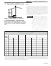
11. Gas supply pipe
The gas supply pipe on this appliance is 1 1/4 or 2" (depending on
model) diameter NPT. Please reference the National Fuel Gas
Code charts for connection details.
12. SMART SYSTEM Control Module
The SMART System Control Module is the main control for the
appliance. This module contains the programming that
operates the blower, gas valve, and pumps in addition to other
programmable features.
13. Air intake
Fresh air for combustion is drawn through a filter provided at the
air intake, located at either the rear or right side of the appliance.
14. Line voltage terminal strip
The line voltage terminal strip provides a location to connect
all of the line voltage (120 VAC) contact points to the unit.
15. Low voltage connection board
The low voltage connection board provides a location to connect
all of the low voltage devices to the appliance. This is where most
of the external safety controls are connected.
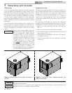
16. Front doors - upper and lower
The front doors provide access to the gas train as well as the
blower, burners and other key components for service and
maintenance.
17. Hot surface igniter (HSI)
The hot surface igniter is a device that is used to ignite the
air/gas mixture as well as monitor the performance of the flame
during operation. This device acts as a flame sense electrode.
18. Flame inspection window (sight glass)
The flame inspection windows, located on either side of the
appliance, allow for visual inspection of the burners and flame
during operation.
19. Manual reset high limit sensor
This device monitors the outlet water temperature to ensure
safe operation. If the temperature exceeds its setting (field
adjustable), it will break the control circuit, shutting the
appliance down. Manual reset is performed through the display.
20. Relief valve
The relief valve is a safety device that ensures the maximum
pressure of the appliance is not exceeded. Pool heaters operate
on temperature and pressure and are shipped standard as 150 PSI
and 210°F (98.9°C).
21. Power switch
The power switch is used to engage and disengage power to the
appliance on the 120 VAC circuit.
22. Air pressure switch
The air pressure switch is a safety device which ensures proper
blower operation. The air pressure switch is wired in series with
the low voltage control circuit in such a way that if the fan does not
engage or shuts down prematurely the device will break the
control circuit and the unit will shut down.
23. Flow switch
The flow switch is a safety device that ensures flow through the
heat exchanger during operation. This appliance is low mass and
should never be operated without flow. The flow switch makes
contact when flow is detected and allows the unit to operate. If
flow is discontinued during operation for any reason the flow
switch will break the control circuit and the unit will shut down.
24. Drain port(s)
Location from which the heat exchanger can be drained. The
drain ports are located underneath the front header.
25. Manual shutoff valve (not shown)
Manual valve used to isolate the unit from the gas supply.
Installation & Operation Manual