


Alarm contacts
The SMART SYSTEM control closes another set of contacts
whenever the heater is locked out or the power is turned off.
This can be used to turn on an alarm, or signal a Building
Management System that the pool heater is down.
Wiring of the cascade
When wiring the heaters for Cascade operation, select one
heater as the Leader. The remaining heaters will be designated
as Members. See page 48, Configuration of the Cascade for a
detailed explanation of this procedure.
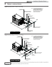
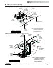
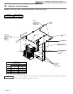
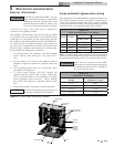
The return sensor of the Leader heater should be placed in the
main system piping loop, upstream of the water being supplied
to all the heaters (see FIG.’s 4-5, 4-6, and 4-7). The return
sensors on the remaining Member heaters may also be placed
in the same location as the Leader or they can be placed in each
Member’s PVC piping loop in the Alternate sensor location,
using the tapped sensor hole (FIG. 4-3). Should the Leader
heater ever need to be replaced with one of the Member heaters
in the Cascade, that Member’s sensor should be relocated to
the previous lead heater’s supply sensor location for optimum
operation of the cascaded units.
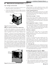
The supply/limit sensors of all cascaded heaters MUST be placed
downstream, in the main system piping loop in the blended
water, going out to the pool (FIG.’s 4-5, 4-6, and 4-7). The
supply/limit sensor also serves as a high temperature limit for
pool supply water and failure to locate all sensors in the blended
water going out to the pool could result in higher temperature
water than desired being discharged to the pool.
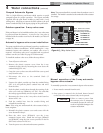
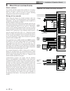
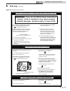
If an external thermostat or BMS is being used to enable or
disable the cascaded heaters, the external thermostat or BMS
should be connected to the Leader heater’s S1 input, located on
the low voltage terminal board (see FIG. 5-5). Jumpers on all
Member heaters should be left in place.
Communication between the Leader and the Member
heaters is accomplished by using shielded, 2-wire twisted pair
communication cable. Connect one of the twisted pair wires to
terminal A on each of the low voltage connection boards, and
the other wire of the twisted pair to terminal B on each of the
low voltage connection boards. Connect the shield wire to the
shield ground terminal on all of the heaters. If more than two
heaters are on the Cascade, daisy chain the wiring from the
Cascade terminals on the second heater to the Cascade terminals
on the third heater, then from the third to the forth, and so
on. The connections can be made in any order, regardless of
the addresses of the heaters. Try to keep each cable as short as
possible.
44
Installation & Operation Manual
5 Electrical connections
ALARM
S
T
A
G
I
N
G
C
A
S
C
A
D
E
M
O
D
B
U
S
CN3
CN2
RUN-TIME
CONTACTS
OPEN
CLOSE
COM
S1
S2
S2
S3
S3
S4
S4
LOUVER
RELAY COIL
LOUVER
PROVING SW
CONTACTS
S1
AQUASTAT
TANK
TANK
SENSOR
SHIELD
A
B
SHIELD
+ 0-10V
- BMS IN
+ 0-10V
- RATE OUT
SHIELD
A
B
SHIELD
35
34
33
32
31
30
29
28
27
26
25
24
23
22
21
20
19
18
17
16
15
14
13
12
11
10
9
8
7
6
5
4
3
2
1
3
-
W
A
Y
V
A
L
V
E
B
TO MONITORING DEVICE
CN2
8
7
6
5
4
3
2
1
20K
POOL
RETURN
SENSOR
LBL20186 REV A
10K
10K
POOL
SUPPLY
SENSOR
NOT
USED
TO MONITORING DEVICE
THREE WAY
VALVE
LOUVER
PROVING
SWITCH
LINE
TO LOUVER
A
B
A
FROM
PREVIOUS
HEATER
TO NEXT
HEATER
EXTERNAL
SEQUENCER/
BUILDING
AUTOMATIC
CONTROL
POOL/BOILER
REMOTE
THERMOSTAT
/EMS
POOL SAFETY
SUPPLY
10K/20K
BK
G
R
W
10K
N/A
N/A
LOUVER RELAY
24VAC COIL
FIELD PROVIDED
OPTIONAL MODBUS
OPTIONAL MODBUS
A
SHIELD
B
A
SHIELD
B
TO NEXT BOILER
N/A
Figure 5-5_Low Voltage Field Wiring Connections