


40
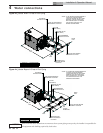
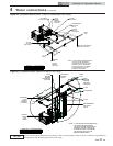
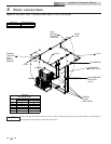
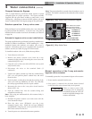
4 Water connections
Installation & Operation Manual
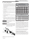
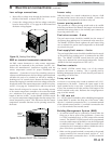
Relief valve
This pool heater is supplied with a relief valve(s) sized in
accordance with ASME Boiler and Pressure Vessel Code, Section
IV. The relief valve(s) is installed in the vertical position and
mounted in the hot water outlet. Place no other valve between
the relief valve and the pool heater. To prevent water damage,
pipe the discharge from the relief valve to a suitable floor drain
for disposal when relief occurs. Do not install any reducing
couplings or other restrictions in the discharge line. The
discharge line will allow complete drainage of the valve and line.
Manually operate the relief valves at least once a year.
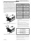
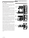
Automatic chlorinator and chemical
feeders
All chemicals must be diluted into the pool water being circulated
through the pool heater. Any concentration of chlorine in the
pool heater can cause damage to the pool heater.
Do not place chlorine tablets or bromine sticks in the skimmer.
High chemical concentrations will result when the pump is not
running.
Chlorinator must feed downstream of the pool heater and have
an anti-siphoning device to prevent chemical back-up in the pool
heater when the pump is shut off.
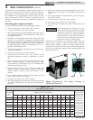
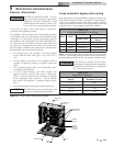
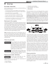
Water flow switch
A water flow switch is standard equipment. The wiring
connection installs the flow switch in the 24 VAC safety circuit
to prove water flow before main burner ignition. The standard
flow switch is installed in the outlet side of the piping loop when
shipped from the factory. These pool heaters require a sufficient
flow of 26 GPM to make the flow switch and start burner
operation.
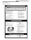
ƽ CAUTION
Avoid contact with hot discharge water.
NOTICE
High chemical concentrations from
improperly adjusted feeders and Chlorinator
can cause rapid corrosion to the heat
exchanger. This damage is non-warrantable.
Ensure that the pump installed on the pool heater will supply
adequate flow to make the flow switch contacts and operate the
pool heater. A water flow switch meets most code requirements
for a low-water cut off device on appliances requiring forced
circulation for operation.
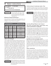
Pump purge delay
Pump purge (pre-running) delay:
The controller provides a pump purge or pre-running feature.
This feature is used whenever the pump has been off for extended
periods of time to conserve energy, causing air to become
entrapped in the pool system piping. The pump purge/pre-
running feature delays pool heater operation until the pump has
been on for a sufficient amount of time to remove air from the
piping. Both the inactivity time and pump purging/pre-running
time are adjustable.
PH-Pump Off:
Inactivity timer is adjustable from 0 to 99 hours. Selection of
time between 4 to 8 hours is recommended.
PH-Pump Purge:
Purge or pre-running timer is adjustable from 0 to 60 minutes.
Selection of a time between 10 to 30 minutes is recommended.
Note: To override the purge/pre-running feature, press the
PREV and NEXT buttons. To disable the feature, the purge/
pre-running timer should be set to zero.