


43
Installation & Operation Manual
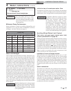
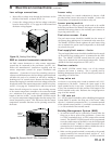
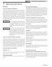
EMS or remote thermostat connection
An EMS, remote thermostat or other remote temperature
control may be connected to the pool heater (see FIG. 5-4).
Follow the manufacturer’s instructions supplied with the
remote temperature control for proper installation and
adjustment. Connection of a set of dry switching contacts or
a remote on/off thermostat to the low voltage connection board
will allow the unit to be switched on and off by making or
breaking a 24 VAC control circuit. Remove the factory jumper
between the Staging S1 terminals on the low voltage connection
board and connect the remote temperature control in its place,
see FIG. 5-5 on page 44. Terminals S2, S3, and S4 are not used.
REMOTE
ON/OFF
CONNECTION
Figure 5-4_Remote ON/OFF Wire Connection
Ensure that all wiring used to connect the switching contacts
of the remote temperature controller to the connection board
are a minimum of 18 gauge and have a maximum installed
length of 300 feet (91.4m). Set the SMART SYSTEM control
to a set point temperature slightly higher than the setting of the
remote temperature control. This will ensure that the remote
temperature controller functions as the operating control for
the heater.
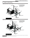
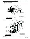
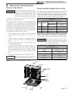
5 Electrical connections (continued)
Low voltage connections
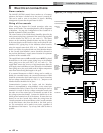
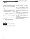
1. Route all low voltage wires through the knockouts on the
left side of the heater, as shown in FIG. 5-3.
2. Connect low voltage wiring to the low voltage connection
board as shown in FIG. 5-5 on page 44 of this manual and
the heater wiring diagram.
LOW
VOLTAGE
KNOCKOUTS
LINE
VOLTAGE
KNOCKOUTS
Figure 5-3_Routing Field Wiring
Louver relay
When the heater is to control combustion air louvers, a field
provided 24VAC louver relay must be installed. Connect the
Louver Relay Coil terminals to the louver relay coil.
Louver proving switch
The operation of a louver proving switch needs to be verified
before the pool heater fires. Remove the jumper wire from these
terminals and connect them to the normally open contacts on
its proving switch (FIG. 5-5).
Pool return sensor - 2-wire
The pool return sensor should be installed into the return of
the primary loop, making sure it is immersed in the water flow.
The SMART SYSTEM control regulates the pool heater firing
rate to maintain the system return temperature to the desired
set point for the pool.
Pool supply/limit sensor - 4-wire
The pool supply/limit sensor should be installed into the supply
of the primary loop, making sure it is immersed in the water
flow. The SMART SYSTEM control limits the pool heater
firing rate to maintain the system supply temperature. Factory
default for the limit temperature is 110°F (43°C).
Runtime contacts
The SMART SYSTEM control closes a set of dry contacts
whenever the burner is running. This is typically used by
Building Management Systems to verify that the pool heater is
responding to a call for heat.
3-way valve out
An electric 3-way mixing valve is used to maintain 130° (55°C)
temperature to the heater. Connect the Open output to the
Open terminal on the 3-way valve. Connect the Close output
to the Close terminal on the valve and the COM output to the
24VAC terminal on the valve. Reference the wiring diagram on
page 39 of this manual.
0 - 10V rate out
A 0 - 10VDC signal is available to allow a Building Management
System (BMS) to monitor the firing rate of the heater. Make
sure the (-) terminal is connected to the (-) or common terminal
of the external control, and the (+) terminal is connected to the
(+) or Vdc terminal of the external control.
Building Management System (BMS)
1. An external control may be connected to control either the
firing rate or the set point of the pool heater. Connect the
0 - 10 VDC terminals to the 0 - 10 VDC output of the external
control. The SMART SYSTEM control can be programmed
to use the enable output of the BMS, or use the voltage signal
to enable the heater. A BMS or a remote thermostat can be
connected to the S1 terminals to enable or disable the unit in
place of the factory provided jumper wire.
2. Make sure the ground terminal is connected to the ground
output terminal of the external control, and the 0 - 10 V
BMS IN terminal is connected to the 0 - 10 VDC terminal of
the external control.