


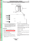
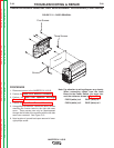
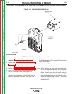


CONTROL
BOARD
MOUNTING
SCREWS
RED CAP
KNOB
WASHER
NUT
FIGURE F.14 CONTROL BOARD REMOVAL
CONTROL BOARD REMOVAL AND REPLACEMENT PROCEDURE (CONTINUED)
PROCEDURE
1. Disconnect power to the INVERTEC® V155-S.
2. Perform the Case Cover Removal Procedure (left
side only).
3. Perform the Input Filter Capacitor Discharge
Procedure.
4. Perform the Input Board Removal Procedure.
5. Perform the Inverter Board Removal Procedure.
6. Using a thin knife blade, remove the red plastic on
the end of the output knob, See Figure F.14.
7. Using a 6mm nutdriver, remove the outpout knob
mounting nut and washer located behind the red
plastic cap previously removed. See Figure F.14.
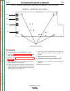
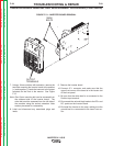
8. Disconnect the JP1 connector.
9. Using a phillips screwdriver, remove the four mount-
ing screws located on the corners of the solder side
of the control board.
10. Disconnect the JP2 connector.
11. Remove and replace the control board.
Note: When installing the new control board, be sure
to turn the output potentiometer shaft complete-
ly counter clockwise prior to fastening knob into
place. This will assure that the output setting is
at itʼs lowest setting. This will allow proper install
ation of the output knob with the red arrow point-
ing to the lowest setting possible. If this is not
done properly, the machine output will not match
the set current.
TROUBLESHOOTING & REPAIR
F-32 F-32
INVERTEC® V155-S
Return to Section TOC Return to Section TOC Return to Section TOC Return to Section TOC
Return to Master TOC Return to Master TOC Return to Master TOC Return to Master TOC